Yeah. My left index. Unsure how to care for it; I'm not going to go get the pulley snapped by a knife. I over-practiced for the open mic last night and my the third song, my left hand was fibrillating instead of playing the chords. I hopefully find there's a sweet spot between not playing at all and going through the songs twice in a day before performing them.The arthritis in my left hand started bothering me after about 15 minutes and I had to take a break after about half an hour and quit entirely after a few shorter and shorter sessions since I missed nearly every note after an hour or so.
Wish I was there, brought my earplugs.
One would think there's still something left. One time I had this 3 or 4 stage / gang volume control and put a section between each stage, so you could turn interstage attenuation up simultaneously. Of course adjustments probably necessary to stagger the attenuation on top of each section, but did Leo think of that?No need to re invent the wheel, whatever " custom" Fender
you think of Leo likely already did it.
What is the cancellation, technically speaking?The second pot can be turned one way to bypass the second stage, the other way to use all of the second stage's gain, or somewhere in between for partial cancellation between the two stages. I prefer a setting that uses just a bit of the second stage gain, nearly full cancellation.
Is this "effect" due to there being too much gain at low frequencies, just blowing the stage into saturation; as even with relatively small C-R coupling, it's only 1st order and the gain more than makes up for any LF attenuation? Or is it a completely different phenom?Any setting past about two or three on the input gain caused blocking distortion in the preamp! Dime the knob, hit a string, and silence happens for up to a second.
Well, I've only read down part way but the first thing that popped into my mind when seeing the welcome mat was "What about those big Plitrons?"
I think the big Plitrons would best be suited for something BIG, since they are rated "400 watts @ 20 Hz." I have no need for a 1 KW HiFi amp but I have all the parts to make one. maybe it will get built someday, maybe not, I don't know.
I have no need for Marty McFly's guitar amp either and I will not build one. I will never be a professional musician. Every kid including myself wanted to be a rock star when they were young. Seeing Jimi Hendrix play live (opening act for the Monkees!) at age 16 let me know that showmanship is just as important as guitar skills. You need lots, and I was a bit short of both. Fortunately for me I met and hung out with a group that had a hit single record in 1970. After spending some time with them and watching what the record company did to them, my rock star aspirations died at age 18 or so. I doubt I'll ever need more than "crank it to 11 outside on the pool deck" kind of volume.
I think the biggest amp I would want to build could have more than one output stage (bi-amped, or Tri-amped) with no more than 50 watts each, probably quite a bit less. The SPP board with 4 old tubes was hitting 44 watts cleanly and it was far too loud to be close to. I have a bunch (over 100) of OPT's that were originally designed for guitar amp use. The spec sheet states "6600 ohms to 0-4-8-16 ohms, 80 VA @ 82 Hz" They work pretty good as 3300 ohm to 0-2-4-8 ohm transformers too. I have seen these things pass over 150 watts of my guitar playing at 3300 ohms into a dummy load and I was intentionally trying to blow one up. I did set one on fire many years ago while attempting a similar test with a pair of 6LW6 tubes running on about 700 volts. Unfortunately, the workbench charring event was due to my Radio Shack quality audio dummy load blowing to an open leaving the OPT unloaded as the power level passed 150 watts. I bought the 8 ohm 500 watt resistors I use now right after that event. I will be making this amp, or amps, with a low budget, so these OPT's will probably be used.
Leo was a great innovator in his time, but one just needs to look at his designs to realize that product cost was near the top of his design criteria. Fortunately, I spent a lot of my engineering design time at Motorola at opposing extremes with respect to product cost. In the cell phone world, every fraction of a cent counts when your run rate is approaching a million units a month. When you are designing a "mission critical" radio for public safety use, and the user's life may depend on it working right every time, cost is no object, after all, it's the taxpayer's money! Leo might have done it all already, but that doesn't mean that it can't be done better. Leo didn't have mosfets or monster sweep tubes either. Note that the first TV sweep tube, the 6BG6G was really just a 6L6G with a plate cap to handle the high voltage.
The little 4 tube 4 watt amp I often use now, and the amp on the silver chassis that I fired up last night were built on a budget, as they were both designed for the HBAC. Whatever I build next will be something I want for myself. I should have enough accumulated "stuff" to make several amps, but I will spend some cash where it actually makes a difference.
The second pot (R17) has signal from V1b's plate (V2a's grid) at one end and the inverted signal from V2a's plate at the other end. Since these two signals are out of phase there will be a point somewhere along the pot where they should cancel each other. In practice perfect cancellation will not occur at all frequencies, or with distorted signals. This is a method of accentuating the harmonics and distortion products in the chain.
I have not yet attempted to find the source of the signal blocking, but I can make a guess or two. As I crank up the drive on the input jack V1a amplifies the signal which is buffered by mosfet Q1. In many guitar amps this buffering is done with the other half of a 12AX7, but I chose a mosfet. That mosfet can exhibit a pretty low on resistance, under 1K ohms, so it can charge C2 far faster than R8 (100K) can discharge it. Over time this will upset the bias on V1b. I can't just lower the value of R8 without risking some blown mosfets, so something else needs to change. Some probing with a scope will be needed. The same scenario could also be occurring with the mosfet that drives the tone stack.
Yeah, I know. I had a moment, seeing you putting a Marshall stack to shame in the yard on July 4th, wailing the anthem . . . . . in a big circle of elevated microwave ovens spewing sparks and melting with plasma. (You know, you're the only member here who gets three full pages of hits on a search for the word 'plasma'.)I think the big Plitrons would best be suited for something BIG,
Well, I guess that might be a sort of bog standard thing in guitar amps, I have no idea, but it just looks like a very cool idea.The second pot (R17) . . . . .
Hhm, looks like in many amps the seconds stage's RC input network is directly driven from the plate of V1a. That presents an additional AC plate load which limits max gain from V1a and also limits voltage swing... but I may ask do we really want/need max gain and swing here?have not yet attempted to find the source of the signal blocking, but I can make a guess or two. As I crank up the drive on the input jack V1a amplifies the signal which is buffered by mosfet Q1. In many guitar amps this buffering is done with the other half of a 12AX7, but I chose a mosfet. That mosfet can exhibit a pretty low on resistance, under 1K ohms, so it can charge C2 far faster than R8 (100K) can discharge it. Over time this will upset the bias on V1b. I can't just lower the value of R8 without risking some blown mosfets, so something else needs to change. Some probing with a scope will be needed. The same scenario could also be occurring with the mosfet that drives the tone stack.
As for the tone stack input buffer, I mentioned in the previous post that I found the last gain stage + cathode follower is of the highest importance and current starving with associated slew-limiting happening on the downward output swing is one of the enemies here. With a stiff MOSFET follower the problem could be certainly worse... and maybe that's indeed what you are seeing here. Scope will tell, I'm looking forward to see what you might find.
Interesting to see if those low Iq followers are the source (pun intended) of the problem. I’m surprised you haven’t scoped it already. Worried that your mosfets can’t handle 200 or so volts at more than one or two mA? Could get completely sacrilegious and go bipolar - Darlington it with a TIP50 and run the damn thing at 10-20 mA. They’ll take 8 watts at full VCE rating, as long as Tj is below 150. You could also reduce the voltage on the tail with a resistor level shifter. That gives a lower tail resistor at the same current (But more VDS, but you can absorb some excess with a resistor/bypass cap in the drain. High enough R in the level shift and it doesn‘t load the first stage much. Bypass the series R. Same trick used in some hi-fi front ends to get the voltage down to work right with a cathodyne. Of course, you could always use tube stages. I’m sure you can find some nice highish gm triodes (or strapped pentodes) in your stash that don’t cost you anything to use here, other than a $1.99 tube socket. BOM cost here is meaningless, if I had a $50 part that I wasn’t using for anything else and solved a problem I’d use it without hesitation on a BUDGET project (but keep looking for another solution if the part wasn’t on hand). It’s not like somebody else has to be able to duplicate the whole thing for $100 here, it’s only out of pocket that matters.
"Interesting to see if those low Iq followers are the source (pun intended) of the problem. I’m surprised you haven’t scoped it already."
I got distracted when I put a real guitar amp OPT in the amp that I apparently built back in 2011 and cranked it up. My immediate reaction is, "Why haven't I been using this thing for the past 9 years" It rocks.
Like the 4 tube, it was built to an extremely thin budget. Both were powered by isolation transformers because they are cheap commodities. Both us a variation of my "way too many diodes" power supplies, again because diodes and caps are far cheaper than transformers. Both use series heater strings that require oddball tubes. The tubes in the 4 tube amp are still on the dollar menu and can be bought for as little as 35 cents each in quantity. The tubes in the bigger amp have gone up a bit since I built it, almost to the point where a 6.3 volt conversion makes sense.
Considering that I have at least 100 octal tube sockets in PCB and chassis mount, and plenty of 9 pin sockets, I got them covered for now. Tubes? Well, I don't know just how many I still have, but I started with over 100,000 tubes that I got free in the 1990's. Many are oddballs, but many are useful. There will be some interesting experiments coming with some circuits and tubes that Leo, or anyone else for that matter has not done in a guitar amp before!
The blocking thins probably has an easy fix, and yes, I could just stuff a TO-220 mosfet in the board and crank up the current, but I haven't even poked around on the board with a voltmeter yet. It worked when I turned it on, so I never looked back.
“6.3 volt conversions“ do make sense - considering that you can simply add 6.3 volt windings on top of those Triad isolation transformers using bell wire. Of course I only buy the toroids (regulation on the EIs is soooo bad). Of course you can do oddball or multiple heater voltages that way too.
When making a “keeper“ project I usually consider winding up a custom power transformer using a donor core that I happen to have, when the number of windings starts going from the ridiculous to the sublime. I collected transformers the way you did tubes, buying up anything cheap that I had potential use for later. Got a boatload of magnet wire from Skycraft while they were still around.
Mosfet wasnt even a TO-220? I was assuming you were using TO-220’s.
I had a large collection of transformers when I lived in Florida. 37 years in the same house does that. My wife was the manager of a rental storage warehouse place, so we got cheap rent and first pickings through abandoned units. Also, I often rode my bicycle around the neighborhood on trash day, picking up electronics, bringing them home, relieving them of useful parts, then dropping the remains in my own trash.
I began the downsizing operation several years before my job ended because I knew that it was inevitable, and we would leave the high cost of living zone when it did. I took lots of tubes, transformers and other sellable stuff to all the local south Florida hamfests for sale, swap, or even free to someone who had a real interest, or even a good story. Tubes that fit old radios usually sold well at hamfests, so that's what I usually took. Nobody had any interest in "worthless old TV tubes" back then. Near the end of a day at a small local parking lot hamfest I got to discussing guitars and amps with someone, who said that he had something that might be worth trading. He returned with the white Stratocaster that is present in some of my old pictures. He left with all the tubes that were left in my Honda Element. Sadly, those small hamfests have mostly disappeared. Despite the efforts to find homes for stuff that I didn't want to move 1200 miles in one of 10 trips with a trailer on the Honda, or pay someone else to move it, I gave over 1500 pounds of transformers and weight bench weights to a metal scrapper for free. Despite my donation to the scrapper, I still stuffed every corner of empty space in the element and trailer on every trip north with tubes, transformers, and other useful goodies. It is likely that any serious guitar amp I build going forward will use 6.3 volt tubes, it is also likely that I have a suitable power transformer for it here somewhere. If not, I will just buy one.
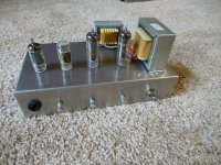
The mosfets are LND150's, TO92's that are at their limit in this thing with 400+ volts of B+ voltage. The board is laid out for the TO92, but I can probably make a TO220 fit.
I began the downsizing operation several years before my job ended because I knew that it was inevitable, and we would leave the high cost of living zone when it did. I took lots of tubes, transformers and other sellable stuff to all the local south Florida hamfests for sale, swap, or even free to someone who had a real interest, or even a good story. Tubes that fit old radios usually sold well at hamfests, so that's what I usually took. Nobody had any interest in "worthless old TV tubes" back then. Near the end of a day at a small local parking lot hamfest I got to discussing guitars and amps with someone, who said that he had something that might be worth trading. He returned with the white Stratocaster that is present in some of my old pictures. He left with all the tubes that were left in my Honda Element. Sadly, those small hamfests have mostly disappeared. Despite the efforts to find homes for stuff that I didn't want to move 1200 miles in one of 10 trips with a trailer on the Honda, or pay someone else to move it, I gave over 1500 pounds of transformers and weight bench weights to a metal scrapper for free. Despite my donation to the scrapper, I still stuffed every corner of empty space in the element and trailer on every trip north with tubes, transformers, and other useful goodies. It is likely that any serious guitar amp I build going forward will use 6.3 volt tubes, it is also likely that I have a suitable power transformer for it here somewhere. If not, I will just buy one.
The mosfets are LND150's, TO92's that are at their limit in this thing with 400+ volts of B+ voltage. The board is laid out for the TO92, but I can probably make a TO220 fit.
Attachments


Going to a single output tube of the push pull is another sound option, might be interesting if one tube could be starved rather than cut completely.It the height of the experiment I had a perf board with 6 octal sockets that could run 1, 2 or 3 pairs of tubes, at the same time, with all three being different types.
Technically it should be horrible (half the waveform..) but I remember it sounding pretty good on a Fender Bassman amp used for guitar, though one 6L6GC was still way too loud before the player got enough distortion using eight CTS 12s", (about seven too many).
Pulling out a single tube on a push pull pair often works better than it has a right to. I’ve had old tube amps that would work fine that way at normal background volume, despite the fact that the unbalanced output transformer should be saturating up a storm.
Never tried it with a toroid (read: cheap) OPT but I bet it won’t like it as much.
Never tried it with a toroid (read: cheap) OPT but I bet it won’t like it as much.
Would it work to switch one of the plates to an ultralinear tap for related effect?Pulling out a single tube on a push pull pair often works better than it has a right to.
If they share the cathode resistor you get a little bit of drive into the other one that way.
The original 4 tube design for the HBAC did not use any semiconductors as per the definition of "tube guitar amp" that was dealt out by the guy who started the whole challenge with his attempt to sell his amp kit here. His design did however use diodes in the power supply. My initial 4 tube amp used a "self split" output stage. The little 70 volt line matching transformer that I used for an OPT really did not like being used as an SE OPT, so the original plan was to leave the second output tube undriven. I experimented with removing the shared bypass cap on the paralleled cathodes and did get a little more power and slightly better sound quality. The input stage was just a typical resistor loaded pentode follower by a simple tone control and a triode gain stage. The amp worked well but lacked that cranked to 11 sound that I wanted, so it wound up in a box after the challenge was over.
4 or 5 years and 1200 miles later the little amp crawls out of the box. The HBAC is over and now there are NO rules. Plating was cut, parts were sky wired in and experiments done. Tuning was done with a box full of pots, some clip leads and several guitars. It looked ugly! There is no "putting this back together again" so a new board was made and amp 1.4 became amp 1.5 The major additions were two LND150 mosfets and the associated caps and resistors. The amp even made its way into a shiny chassis.
One mod created a variable input impedance "gyrator" load on the input pentode which I called the Saturator circuit. So named because a pentode running into a 1 megohm or higher load impedance will swing from the plate supply voltage to its saturation voltage with just a few millivolts at its input. The pot can be used to dial back the gain into wimpy triode territory (about 10X) or anywhere between these extremes.
The other LND150 became a split load phase inverter transforming a self split output stage into a real push pull stage. The transformation resulted in more power output, about 4 watts as compared to about 2.5 watts. It also resulted in a far better overdriven sound where hard clipping was possible. Even at 170 volts of B+ it was now possible to make the screen grids glow in the wimpy 32ET5 tubes. I raised the shared screen resistor to 2.7K and hung the whole preamp's supply line on the tube side of that resistor. Now the little amp has a "sag" effect somewhat like the tube rectifier effect.
I expect my neat looking preamp board to experience some similar changes before I'm done here.
Experiments I did many years ago revealed that the actual plate voltage on an output tube in a properly functioning guitar amp driven to clipping at or near the speaker's resonant frequency can be in the kilovolt range. I saw spikes of about 2500 volts in a working push pull guitar amp with a 430 volt B+ using KT88 tubes and one of my cheapie 6600 ohm OPT's that were designed for guitar amps. Most guitar speakers have their resonant impedance peak within a standard guitar's frequency range. Operation at resonance while the amp is overdriven is a high probability.Would it work to switch one of the plates to an ultralinear tap for related effect?
A switch on the primary side of a vacuum tube amp might not be such a good idea. I used to use "appliance switches" in the primary circuit of my SSE amps without issue, but they generally don't get used well into clipping into a severely mismatched load.
Note that is also not a good idea to stick a typical scope / probe on the plate of a tube and drive the amp into clipping. I used a 10:1 external divider with a string of resistors during my testing.
Attachments


Even if bypassed with a capacitor? I did the switch to shut off one side but the amp was mostly in Class A anyway.If they share the cathode resistor you get a little bit of drive into the other one that way.
On upsetting the output stage applecart, a master volume is also fun. One thing I have wanted to try is to have a switch on the MV (dual pot with P-P switch) and bypass the pot on one side of the signal. So one side gets full signal and the other side gets dialed down to taste for a (hopefully) thicker sounding clean sound.
Not a bypassed cathode resistor. That shorts out the differential path between the cathodes. Shared cathode R’s often are not bypassed, which will give more differential gain than common mode. Individual ones usually are bypassed because you don’t want the reduction in gain.
The "self split" output stage uses the typical pair of output tubes with a shared resistor and no bypass capacitor. The grid of one tube is driven while the other is grounded. The low value of the typical cathode resistor makes for a poor CCS, but some signal is coupled through the cathodes so there is some cathode drive to the second tube. If the amp was truly biased in class A all the time, a true CCS could be placed in the shared cathode for good performance. A typical guitar amp leaves class A as soon as the player "sets the controls for the heart of the sun' stomps on the KILL pedal and thrashes away, no matter what the marketing team may call it.
I found that the wimpy 32ET5 tubes could not be driven hard enough for good sounding distortion with a self split arrangement, so I added a true PI and went on from there. Once I drove both grids properly the sound got better. If the amp stays in Class A, a shared bypass cap is not necessary as the opposing signals on the cathodes cancel. Once you severely overdrive the output tubes, a cap seems to tame the mess a bit.
I found that the wimpy 32ET5 tubes could not be driven hard enough for good sounding distortion with a self split arrangement, so I added a true PI and went on from there. Once I drove both grids properly the sound got better. If the amp stays in Class A, a shared bypass cap is not necessary as the opposing signals on the cathodes cancel. Once you severely overdrive the output tubes, a cap seems to tame the mess a bit.
- Home
- Live Sound
- Instruments and Amps
- Tubelab wants a new guitar amp