Some people here know that I started out building guitar amps as a kid in 60's. In a time long before the internet was even a dream, the only way to learn how guitar amps worked was to take one apart. Anything I found in the trash was usually a hot chassis shocker or a popular 50's vintage amp that was beyond repair. My father decided to upgrade the old Magnavox mono console HiFi to a stereo console and the Maggie became my guitar amp by splicing half of a guitar cable to the wires in the tone arm with masking tape. Oddly the creation sounded pretty good and was plenty loud with a pair of 6V6 tubes driving two or three speakers.
One day the older brother of a school mate who worked at a radio station and was a ham radio operator decided to take his younger brother's Fender Champ apart. We traced out it's schematic and I had a place to start. Several smoking failures later, I had DIYed my first real guitar amp using parts recycled from dead TV sets. Several interim amps were constructed and by the time I was in high school I had a bunch of amp clones both tube and solid state. After a few years of consumer electronics repair I got a job at a Motorola plant where we could get free silicon (within reason) by filling out a sample request form. All my amp builds both HiFi and guitar were silicon based life forms from the early 1970's well into the 1990's.
The Motorola job was my escape from the reality that was running the service department at an Olson Electronics store and living in my parents' house. The separation did not occur on the best of terms and most of my "stuff" was left behind and subsequently discarded. My Hagstrom guitar was stolen sometime in the early 70's so I didn't play guitar at all for a few years. I got a Univox guitar in about 1976 and a dead Kustom amp sometime later. I still have the Univox, but fixed and sold the Kustom within a few years. Several guitars and amps came and went over time, but I never took it seriously and my playing skills have degraded pretty badly. After 41 years at Motorola, I retired and moved north. I gave away the unique Ulraflex / Magnatone guitar amp with two uniquely voiced power amps each feeding a different sized speaker in the combo cabinet due to lack of storage space. I liked the wide range of tones that amp could produce.
Sure I can (and do) stick the guitar cable into the Focusrite and call up any one of several killer amp sims on my PC and jam with some backing tracks from a DAW, but..........
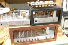
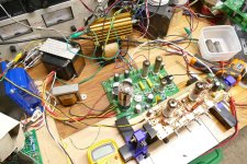
I look around the room and I can see 10 guitars or basses and a few more in pieces, but no real amp. The Hundred Buck Amp Challenge got me to build a few amp prototypes, four of which are pictured here. The little 4 tube unit in the black case is the only one that still works, though the 5 tube unit on the bottom just needs an OPT, as I "borrowed" the one it had.
I have the skill set and knowledge to make just about any amp I want, but I can't make up my mind what that is, so nothing has been built. The music I grew up with and played from age 12 on was 60's surf music, so reverb is a "must have." The little 4 tube 4 watt amp is loud enough in the concrete basement, but falls short outside with my 91 dB speakers, so more power and better speakers are a given. My musical tastes wander from mellow to metal, and I occasionally will beat on a bass guitar, so it's hard to figure out what kind of amp or amps to make.
For another perspective, I looked at all of what's out there today and watched far too many YouTube videos to realize that much of it all sounds the same. The Hughes and Kettner Triamp Mark III looks like the most flexible design out there, but it is $4000! I like, and will likely use the idea of multiple preamps and multiple power amps with relays or other means of switching them. I'm sure that there will be several roadblocks and detours on this journey, but I need to start somewhere.
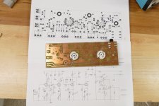
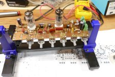
Obviously, this idea has been kicking around inside my head for quite some time, since I found an unbuilt DIY PC board in my junk box that had a pair of 9 pin sockets, a 1/4 inch jack and places for 6 pots. It had a 2011 date on it so I made this when I was still working at Motorola and living in Florida. A journey through my 10 TB hard drive found a matching Eagle layout with an associated schematic. It looks like a typical 4 stage Fender, Marshall, Vox preamp without a phase inverter, so I must assume that I intended to drive one of my existing amp boards with it, most likely the SPP which uses EL84's. Yesterday I had a nearly empty PC board. Today I have one that is populated, albeit with whatever I could find quickly in between periods of shoveling snow. Now I have a place to start. I will apply power today, in between some more snow shoveling.
Any thoughts or ideas on features to include and comments in general are welcome. If I follow this path wherever it leads me there will likely be more than one amp created. I have created an output stage concept called UNSET that works well for HiFi. It needs to be tried for guitar amp use as well.
One day the older brother of a school mate who worked at a radio station and was a ham radio operator decided to take his younger brother's Fender Champ apart. We traced out it's schematic and I had a place to start. Several smoking failures later, I had DIYed my first real guitar amp using parts recycled from dead TV sets. Several interim amps were constructed and by the time I was in high school I had a bunch of amp clones both tube and solid state. After a few years of consumer electronics repair I got a job at a Motorola plant where we could get free silicon (within reason) by filling out a sample request form. All my amp builds both HiFi and guitar were silicon based life forms from the early 1970's well into the 1990's.
The Motorola job was my escape from the reality that was running the service department at an Olson Electronics store and living in my parents' house. The separation did not occur on the best of terms and most of my "stuff" was left behind and subsequently discarded. My Hagstrom guitar was stolen sometime in the early 70's so I didn't play guitar at all for a few years. I got a Univox guitar in about 1976 and a dead Kustom amp sometime later. I still have the Univox, but fixed and sold the Kustom within a few years. Several guitars and amps came and went over time, but I never took it seriously and my playing skills have degraded pretty badly. After 41 years at Motorola, I retired and moved north. I gave away the unique Ulraflex / Magnatone guitar amp with two uniquely voiced power amps each feeding a different sized speaker in the combo cabinet due to lack of storage space. I liked the wide range of tones that amp could produce.
Sure I can (and do) stick the guitar cable into the Focusrite and call up any one of several killer amp sims on my PC and jam with some backing tracks from a DAW, but..........
I look around the room and I can see 10 guitars or basses and a few more in pieces, but no real amp. The Hundred Buck Amp Challenge got me to build a few amp prototypes, four of which are pictured here. The little 4 tube unit in the black case is the only one that still works, though the 5 tube unit on the bottom just needs an OPT, as I "borrowed" the one it had.
I have the skill set and knowledge to make just about any amp I want, but I can't make up my mind what that is, so nothing has been built. The music I grew up with and played from age 12 on was 60's surf music, so reverb is a "must have." The little 4 tube 4 watt amp is loud enough in the concrete basement, but falls short outside with my 91 dB speakers, so more power and better speakers are a given. My musical tastes wander from mellow to metal, and I occasionally will beat on a bass guitar, so it's hard to figure out what kind of amp or amps to make.
For another perspective, I looked at all of what's out there today and watched far too many YouTube videos to realize that much of it all sounds the same. The Hughes and Kettner Triamp Mark III looks like the most flexible design out there, but it is $4000! I like, and will likely use the idea of multiple preamps and multiple power amps with relays or other means of switching them. I'm sure that there will be several roadblocks and detours on this journey, but I need to start somewhere.
Obviously, this idea has been kicking around inside my head for quite some time, since I found an unbuilt DIY PC board in my junk box that had a pair of 9 pin sockets, a 1/4 inch jack and places for 6 pots. It had a 2011 date on it so I made this when I was still working at Motorola and living in Florida. A journey through my 10 TB hard drive found a matching Eagle layout with an associated schematic. It looks like a typical 4 stage Fender, Marshall, Vox preamp without a phase inverter, so I must assume that I intended to drive one of my existing amp boards with it, most likely the SPP which uses EL84's. Yesterday I had a nearly empty PC board. Today I have one that is populated, albeit with whatever I could find quickly in between periods of shoveling snow. Now I have a place to start. I will apply power today, in between some more snow shoveling.
Any thoughts or ideas on features to include and comments in general are welcome. If I follow this path wherever it leads me there will likely be more than one amp created. I have created an output stage concept called UNSET that works well for HiFi. It needs to be tried for guitar amp use as well.
Attachments
One feature that seems paramount to me is the ability to get 'that tube sound" at any volume level from bedroom quiet to club level loud. Perhaps something along the line of London Power's scaling idea. Adjustable, switchable "grunge". Reverb a must (as you said). Perhaps negative feedback switch in/out. Tremelo. Channel switching. Selectable output impedance transformer.
Hopefully it will be an amp that you can play, as part of your instrument. One that you can control the sound of with your fingersI can't make up my mind what that is, so nothing has been built.
")
At this point, I have not decided. If I chose to take this road again (been down it several times in the past) there could be several different amps built in various power levels. Marty McFly type levels would be way down the list though. I would venture to guess that I have made between 50 and 100 guitar amps in the past 50+ years. The ones that saw the most real use by real guitar players were all 50 watts or less. The typical venue was a bedroom, college dorm room, or maybe a small stage in a club or bar. I have no need for 1.21 Jiggowatts, nor the parts to build Marty's amp and huge speaker. I am digging through my collection to see what I do have, especially in the speaker department. I have found over 20 speakers suitable for use in a guitar or bass amp in sizes from 5 inch to 15 inch. All are at least 10 years old. Most are rated from "15 watt to 35 watt" except for the 15 inch "pro audio" speakers.So how many watts do you want to make here? Marty McFly or just typical stage volume?
I have a large quantity NOS of 6600 ohm to 0-4-8-16 ohm "80VA" OPT's that were originally built for ADA guitar amp duty. They work well as 3300 ohm to 0-2-4-8 ohm too. I have squeezed over 100 watt through them in guitar amp use at 3300 ohms reliably with no issues.
The last time I made several amps was the late 1990's when my daughter was the drum captain in the high school band. All were built at ultra low cost for a reason. The back room of our house had a drum cage full of drums, a Roland JV-1000, and a POS "Brownsville" 100 watt solid state guitar amp that was used for the Roland. The room was occupied by "HS band geeks" for most of the time. Guitars were amplified by between two and five of my DIY guitar amps, all tube, and either a variation of my "Turbo Champ" or a "Fender inspired" push pull tube amp that made between 25 and 40 watts depending on what I stole the power transformer out of. Oddly, many of the Turbo Champs used some combination of car audio speakers that I got cheap when a local K-Mart closed down. As HS graduation day drew close, I gave all of those DIY amps to the kids that used them. The Brownsville was sold to a neighbor. I still have, and recently rebuilt the JV-1000. I also have some of the drums, but most were lost.
Is there such a thing as a parallel push-pull ?? A string of 6V6 s' ??
------------------------------------------------------------------------------------------------------------------------Rick...
In my ventures through hamfests for more than 40 years I have collected a box full of 1940's and 1950's vintage metal octal vacuum tubes. That box includes six metal 6V6 tubes. In a random Ebay purchase I recently got a few metal 6L6 tubes too. These along with a handful of smaller tubes will be used to build an amp I will call MetallicAmp, all tube, no glass. The idea is to create something that Leo could have been made in the 1950's. All parts will be something that existed in the late 40's and early 50's, but not necessarily that old. IE, a new production relay or CDS photoresistor can be used, but an LED or transistor cannot. Why? I don't know, maybe it's more of a why not? 10 to 25 watts would be the target here.Six 6V6’s? (Or more likely 6W6). The devil’s amp. Highway to Hell.
Much of my experimentation will be centered around the exploration of the UNSET configuration in guitar amp use. The current UNSET circuit has a mosfet follower driving the cathode of the output tube. You couldn't get mosfets from Mouser or Digikey in the 50's since none of the three existed yet. It is possible to do UNSET with a driver transformer, but this requires some considerable power in the driver. If MetallicAmp gets UNSET, it will be via a driver transformer. The next experiment will be a pair of 6V6's driving a pair of 6L6's through a transformer.
Other than the MetallicAmp experiment, I don't know where I'm going. I would like to use the stuff that I have to keep costs down, but I have a lot of stuff.
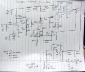
I am including the "best guess" schematic of the Turbo Champs I built in the 90's. All were different as they were made with whatever I had available at the time over a 3 year period. This schematic was drawn from memory after the fact. Most amps used a Chinese KT88 for the output tube. A few used a Chinese 6L6GC. Most used the Hammond OPT, but only a few used the Allied 6K7VG power transformer. Most used transformers robbed from scrap HP 200 series vacuum tube audio oscillators.
Attachments
Tubelab, Are you planning on a separate board for the reverb driver/recovery and if so, will it be integrated into the preamp section?
Personally, I like the range of about 20 watts for the power amp. 20 to 30 watts can get a very respectable volume even outdoors (mic for PA).
Personally, I like the range of about 20 watts for the power amp. 20 to 30 watts can get a very respectable volume even outdoors (mic for PA).
At this point everything will be built and tested on whatever prototyping style suits me at the time. The guitar preamp board was something I thought up back when I often had spare time with a laptop and some ideas while stuck in an airplane, car or hospital waiting room. There are dozens of PC board designs on my hard drive in various stages of completeness, but the guitar preamp made it to copper before being stashed in a box. It is now populated but has not seen power yet.
Some of my protos are simply parts sky wired on top of an old PC board design, some are made on turret boards and some even got built with parts and clip leads. Once something begins to take shape, I'll think about making a PC board for it. Just how the board or boards get partitioned will likely be discussed here as the design progresses.
A large and complicated amp will need to be divided into more than one board if it will ever be a Tubelab product simply because of shipping restrictions. The largest board that I can economically ship worldwide is 8.5 X 5.5 inches.
Right now, my thought is to use one my existing boards, the UNSET, SSE, and SPP for the power supply and power amp section and hack them up as needed for the power supply and power amp sections.
Once something begins to take shape, I'll think about making a PC board for it. Just how the board or boards get partitioned will likely be discussed here as the design progresses.
That sounds like a good plan, looking forward to the process! CheersRight now, my thought is to use one my existing boards, the UNSET, SSE, and SPP for the power supply and power amp section and hack them up as needed for the power supply and power amp sections.
Subscribed! Making your own guitar amp and tailor it to taste is fun and very rewarding, emotionally.
Food for thought... the nice thing is that you can do things not seen in all those factory "standard" preamp circuits.
I'm a master volume type of player, that is, the power amp shall not add any unstable and level-dependent coloration. I never was fully satisfied with any of the stock overdrive/distortion sounds from many amps I had, but the classic Marshall Lead 2203/2204 preamp section was a good starting point.
Years later, it finally led to a very non-standard dual mixed signal path, besides the usual tinkering with operation points and interstage RC circuits, including the tone stack.

I can share more details/description if interested.
Food for thought... the nice thing is that you can do things not seen in all those factory "standard" preamp circuits.
I'm a master volume type of player, that is, the power amp shall not add any unstable and level-dependent coloration. I never was fully satisfied with any of the stock overdrive/distortion sounds from many amps I had, but the classic Marshall Lead 2203/2204 preamp section was a good starting point.
Years later, it finally led to a very non-standard dual mixed signal path, besides the usual tinkering with operation points and interstage RC circuits, including the tone stack.
I can share more details/description if interested.
Last edited:
Any and all ideas are welcome. As far as the schematic in post #11 is concerned, I am interested in where the "from EL34 bias" connection goes. The path through R17 and C12 is reverse phased compared to the path through the tone stack. Both paths have frequency dependent phase shifts, so this could lead to some unique tone control action.
Pot R17 in my schematic from post #1 has an out of phase signal at each end. This should and does lead to a near perfect cancellation of the output signal at some position of the pot.
I now have the board fired up and running on a bench power supply and fed with an audio oscillator. The cancellation is near one end of the pot, but things will change when I hook up a guitar, a power amp board, and go poking around with capacitors.
I think you've been part of any thread on tube guitar amps I have ever participated in so I am not sure I can give you any new ideas.
About the only thing that comes to mind is I have a PCB that has optionality to either built a vintage dual-input circuit, or to build as single input with the extra triode section creating a more modern high gain channel.
About the only thing that comes to mind is I have a PCB that has optionality to either built a vintage dual-input circuit, or to build as single input with the extra triode section creating a more modern high gain channel.
The "from EL34-Bias" connection goes to the top of the bias pot and just provides a negative DC voltage for the circuit, in order to clip the negative wave coming from the cold clipper stage V1b. That extra clipping is not essential to the sound, though.Any and all ideas are welcome. As far as the schematic in post #11 is concerned, I am interested in where the "from EL34 bias" connection goes. The path through R17 and C12 is reverse phased compared to the path through the tone stack. Both paths have frequency dependent phase shifts, so this could lead to some unique tone control action.
Pot R17 in my schematic from post #1 has an out of phase signal at each end. This should and does lead to a near perfect cancellation of the output signal at some position of the pot.
I now have the board fired up and running on a bench power supply and fed with an audio oscillator. The cancellation is near one end of the pot, but things will change when I hook up a guitar, a power amp board, and go poking around with capacitors.
And yes, the partly subtractive and non-EQ'd nature of the summing happens to be a key point (I tried with additional LND-150-based inverter first and failed. I also tried mixing in at the input of the tone stack but also not good result). As long as the last stage V2a+V2b doesn't severely clip the contribution from the additional path is microscopic.
When it goes into heavy clipping, more of the second path becomes effective in the sum, basically reducing the fundamental, making the sound brighter and more aggressive.
Finally, when the cold clipper itself maxes out with strong input, the produced extra distortion is partly added in directly, again with a somewhat destructive summing. This gives sort of extra "definition" and attack, the harder you dig in on the guitar the "crazier" the distortion gets... to the point of ending up with a total mush of noise when strumming complex chords at full might ;-)
The tone controls double up as mixing controls for the additional path, the lower the settings the more of the secondary path comes into play. Not perfectly versatile but adding an accessible extra pot was not an option.
The second important aspect of the channel is the distortion behavior of the gain+CF stage, loaded by the tone stack. It is this stage that saturates and clips first, after all.
In the stock circuit, V2b often starves current on fast downward swings, provoking slewing distortion, the voltage cannot go lower faster than the discharge rate of the tone stack main cap allows, also depending on tone control settings quite a bit. This is part of the trademark 2203/2204 bite but prevents a nice smooth and gradual reduction of distortion in the decay of a note.
With a lower cathode resistor and larger anode resistor of that stage it develops distortion with level much earlier but also extremely gradual which is my strong personal preference. The final touch comes from the sightly modified cold clipper stage and its input and output networks to balance things out.
The reaction to playing style, guitar volume/tone controls and guitar type of this channel is brutal and exaggerated but highly addictive, for me at least it is. For others, it might be unplayable.
With conventional high(er) gain stages OTOH, the distortion character does not change much once past a certain gain, it just decays much slower. I'm not saying this is a bad thing, it's just different.
I'd vote for the transformer driven output stage. Probably because I did that once; literally put a single ended transformer stage upstream of a push pull. Not to say that's what to do, but I'll guess such an architecture just might be different enough. Like the old 60's tape recorder amplifiers always had a driver tranny.
Another "fun trick" might be to create an output / preamp stage circuitry that would auto bias whatever you put into it. Back when, I recall a fellow engineer telling me about such an amp in the SS realm; said you could put anything in the circuit - as long as it was at least the N or P type part in the correct spot - and the amplifier would bias that component correctly; FET, BJT, didnt matter. I wonder if there's a tube equivalent of that idea? Like, how would the circuit know what tube someone put in, to make the most out of it, without going over?
6, 6V6s is interesting. How about an output stage that solves the power problem by "depends on the number of tubes you put in"? A 10W bedroom amp, you put two. A Club amp, put in all six. An amp design that would "accept" as many socket as you care to wire up and have the heater current to make glow. Load up the P-P output sockets asymmetrically if you want; the amp doesnt care a bit, because it can solve the P-P output tranny balancing act electronically. Maybe it just sounds different when loaded that way.
Maybe make a better power supply; one that has controllable characteristics unto each tap. Sometimes a power supply will "collapse" just right to give a compression effect in a tube amp with all different time constants between the output stage and preamp B+ connections. What if the power supply had a "load line" that was like a series resistor, but adjustable with a control (and actually a series pass tube or FET) ? Perhaps it could be made to behave as if there was a capacitor there too, only there'd be a control of the "virtual" amount of capacitance the powered tube circuit would see at its B+ connection.
Just thinking of stuff that would have not been possible "back before the internet" but now! I know you're a true Whiz at this stuff and I'd bet you could do it all if you wanted to.
Back in the 1980's I believe, a friend brings me a Fender Bandmaster with a burnt tube socket. Simple fix, right? As I dig into the amp I notice a mishmash of tubes in the amp including one 6L6GC and one EL34 in the output stage. I asked the owner what was up, and he told me that several months prior he and a friend decided to play musical tubes with two different amps, the other being a Marshall. Some of the preamp tubes had been switched around as well. They had also experimented with different speaker cabinets and I suspect that this is where the burnt tube socket happened. Two new ceramic octal sockets left them happy with their creations, and got me thinking and experimenting a bit, as the Fender did have a unique character to it.
It the height of the experiment I had a perf board with 6 octal sockets that could run 1, 2 or 3 pairs of tubes, at the same time, with all three being different types. This was the bridge too far, but I did build a few amps with 2 pair of dissimilar output tubes selectable with switches in the cathode circuit to disable a tube. Much like the Turbo Champ, all three different speaker impedances were switch selectable as a mismatch often gives a desirable effect for some players / music. The most popular combos were a pair of EL34s and a pair of 6L6GCs. Each pair, both pair, or one of each tube could be used. Another combo had a fixed 3 tube output stage with a pair of 6V6GT's on one side of the OPT and a single 6L6GC on the other.
Today we can stick a computer brain in just about anything, maybe throw in a little Artificial Stupidity for marketing points. The most feature packed guitar amp I could find in my searching through several of the internet music stores is the Hughes and Kettner Triamp Mark III. It also has three pairs of switch selectable output tubes, one pair of EL34's and two pair of 6L6GC's usable in combinations of one to three pair. The amp appears to contain three preamps, and three power amps each voiced differently, and selectable in multiple combinations. The user manual is a worthwhile read and available online. I have found schematics and service manual for the Triamp Mark I online, but not the II or III.
https://hughes-and-kettner.com/wp-content/uploads/2015/01/TriAmp_Mark_3_BDA_1_1_7spr.pdf
I have collected a lot of "stuff" in the 50 some years that I have been making things. There is an abandoned mobile home on our property that I use for storage. It is unheated and not exactly perfectly sealed, so I tend to store things there that don't mind temperature extremes. Things like chassis, old dead stuff and boxes full of tubes.
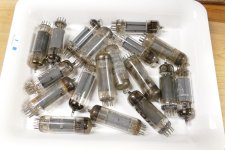
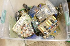
Last night I saw the little preamp work so I set out to connect it to a power amp. That's where progress stopped. I got out a known working Tubelab SPP board and proceeded to connect the preamp to one of its channels. Uh, it seems that I have zero EL84's in this house. There are some in the trailer, but there is only one way into the trailer as the front door is secured from the inside. The back door opens outward and has at least a foot of snow piled against it. I wasn't about to go digging in the dark up on a rotten deck with no handrail, so I turned to a box that has not been opened since I left Florida. The box was labeled "OLD TUBES" and did contain a bunch of stuff that was hastily boxed up in a hurry. I was tinkering with guitar stuff at the time, so.......
Once opened I found about a dozen more metal tubes to add to the growing list of possible "test subjects" for MetallicAmp, and 18 rather crusty looking tubes that might be 6BQ5's or EL84's. This box came from the time that I stripped about a dozen vacuum tube HP audio oscillators for their electronics because they were destined for the metal scrapper. This means that all the HP branded tubes will be 6CW5's. Maybe a pair of those crispy looking Magnavox tubes will make sound in an SPP board. I am about to find out as soon as I find one of the power transformers that I stole from the HP signal generators.
Attachments
Another idea I tried in the long dark past was a fully differential design. I had got this green Altec tube PA head at a local flea - with plenty of mixer stages that I decided I could rewire any way I wanted. So I put the phase splitter as the very first tube in the signal chain and everything on down to the 6L6 outputs used dual potentiometers.
Almost sold it to a guy who was astounded at what he said was a EL34 sound I was getting out of 6L6s. He never returned with the money... That amp vanished somewhere in the fires of life.
Phase splitter as the first tube followed by a fully diff circuit is just an uncommon idea. No one in their right mind manufacturing would do it, as it's probably a waste of tubes - why spend twice as much doubling up on everything? Then again, if it makes a certain sound, it doesnt matter how many tubes it takes, as that's priceless.
I figured if anyone had already done this... ;')
Almost sold it to a guy who was astounded at what he said was a EL34 sound I was getting out of 6L6s. He never returned with the money... That amp vanished somewhere in the fires of life.
Phase splitter as the first tube followed by a fully diff circuit is just an uncommon idea. No one in their right mind manufacturing would do it, as it's probably a waste of tubes - why spend twice as much doubling up on everything? Then again, if it makes a certain sound, it doesnt matter how many tubes it takes, as that's priceless.
It the height of the experiment I had a perf board with 6 octal sockets that could run 1, 2 or 3 pairs of tubes, at the same time, with all three being different types.
I figured if anyone had already done this... ;')
I started down the fully differential road long ago, but it was intended to be more like a vacuum tube opamp with a single ended cathode follower output stage. It turned out to be a very good TV and radio jamming device that could even interfere with wired cable TV. After a couple days of trying to tame the beast, it went into the dead projects box.
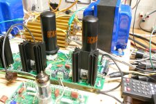
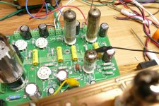
Speaking of the dead projects box, it always has a unique aroma every time I open it. It smells like burnt parts. I wonder why. I cracked open the box yesterday to fetch 3 Tubelab SPP boards. Two were known to be working at one time, and a third was never finished. I was planning to use one of three power transformers that I robbed from HP audio oscillators to power this amp, but after trying to connect the (too short) solid core 5 and 6.3 volt heater windings to different sides of the board with zero results and lots of frustration, I looked at the shelf full of transformers. This Mercury Magnetics replacement transformer for a Fender Bandmaster jumped out onto the bench and wrapped its virgin foot long wires around the board all by itself. Now, I know that a bandmaster (2 X 6L6GCs for about 50 watts) eats more than my experiment wants, so my stuff must be prepared to suffer indigestion from over eating.
Running a 5U4 with no load gets 516 volts on 450 volt electrolytics. I stick the first pair of crusty Magnavox 6BQ5's into the board and plug it in. The B+ is now 465 volts and I get 29 watts of audio power at 3% THD and 0.46% THD at 10 watts (power amp board only at this time). I'm going to stuff a second pair into the board and wire them in parallel with the first pair. Maybe that will bring the voltage down a bit.
Attachments
- Home
- Live Sound
- Instruments and Amps
- Tubelab wants a new guitar amp