I lifted one end of the coupling caps on the second pair of tubes and wired then in parallel with the first, paralleled the plates, then rewired the OPT for 3300 ohms. Idle B+ is now 420, still too much for the screen grids. I cranked it up until I reached 3% THD where I get 44 watts. B+ at this level is 396 volts. Not bad for 6 old tubes.
Attachments


What is the crossover distortion like in clipping? Or would that be too much for them given the operating conditions. Mind you, would not want you to blow them and have to go shoveling.
I thought of the parallel path thing a bit when going down the tube compressor rabbit hole. Thought of a Fet up front splitting the signal.
I thought of the parallel path thing a bit when going down the tube compressor rabbit hole. Thought of a Fet up front splitting the signal.
As it is now the tubes are operating way beyond spec, so I need to swap out the power transformer before the inevitable meltdown occurs. I don't know where these tubes came from, but the box they were in was packed 10 years ago and I probably had them for some time before that. I was surprised to see that the first 4 I tried actually worked. These tubes are cathode biased with a 270 ohm resistor. The cathode voltages ranged from 14.5 to 15.9 volts, so they are not exactly "matched." With about 400 volts across the tubes at idle, they are cooking at 21.5 to 23.5 watts assuming matched cathode resistors (not). I'm not so sure that my preamp will survive this voltage either, all of the electrolytics in both boards are rated for 450 volts. Cold tube startup hits 515 volts.
The distortion as the amp clipped appeared to be due to the clipping itself. No crossover distortion or notching was noted. THD at 1 watt was 0.24% so crossover at idle is not an issue but might be at a more reasonable operating point.
I doubt that I will use 6BQ5 / EL84 in the finished amp, they were just the quickest path to a working power amp with a multi tapped OPT secondary. Most of my suitable SE OPTs have a single secondary. I have two existing "guitar" speaker cabinets available currently for testing, and both are 4 ohms. One has a pair of ElectroVoice EVM10M speakers. They are LOUD @99 db each, but very heavy. The other has a pair of Parts Express 6 inch "pro audio" speakers which are not so loud at 91. something each.
As it is now there is a volume pot after the first stage plus a MV pot at the preamp output. Parallel path(s) would likely come from a second (or more) pot across the first volume control. It is bufered from the 12AX7 by a mosfet follower so several pots could be paralleled at that point.
I kinda like the idea of being able to select either a pair of EL84 or a quad of them. It's still a ''reasonably'' priced tube and commonly available.
Makes a nice wattage range about 15W paired and 30W with the quad selected.
That you got it working at 400V and 20+ watts dissipation, without the light and smoke show.. amazing! But yeah, probably not for long ;-) Cheers!
Makes a nice wattage range about 15W paired and 30W with the quad selected.
That you got it working at 400V and 20+ watts dissipation, without the light and smoke show.. amazing! But yeah, probably not for long ;-) Cheers!
My brain has been powered by it for over 70 years."Artificial stupidity"
I love it!
If I was to build a vacuum tube guitar amp for use, by the average guitar player it must use tubes that are available to them or their repair techs. For most, that's a very short list.
If I was to build a guitar amp just for myself, I would pick from something that I have a lot of. Lets just say that I have several hundred 6GF5's and I can squeeze 80 watts from a pair of them without any complaints from the tube. The 6GF5 was on ESRC's dollar list for several years. Even at $1 each, nobody bought any, so I got 10 "tested" and bought several hundred for 35 cents each! The picture shows the 6GF5 next to a 6V6GTA. The 6GF5 is either a 6BQ6GA or a 6DQ6 with its plate wings clipped and stuffed into a small bottle. Virtually nobody has even heard of the 6GF5, so that amp would be useless to anyone but me.
There is however some middle ground. If this evolves into a Tubelab board, or more likely a set of boards, the power amp and power supply would likely be on one board, and all the small signal stuff on another board. This would allow multiple possible configurations, so a 20 watt bedroom blaster or a 200 watt voice coil destroyer could share a common preamp board.
The 6DQ6 and 6BQ6 medium sized TV sweep tubes are pin compatible with the common octal guitar amp tubes. It is possible to run them in the same socket, though not under the same conditions.
Attachments

Isnt this an opportunity to try a series pass regulator? I bet you have plenty 6080 / 6AS7s around. A variation onWith about 400 volts across the tubes at idle, they are cooking at 21.5 to 23.5 watts assuming matched cathode resistors (not). I'm not so sure that my preamp will survive this voltage either, all of the electrolytics in both boards are rated for 450 volts. Cold tube startup hits 515 volts.
https://www.diyaudio.com/community/threads/fully-tube-regulated-psu.378245/
There are lots of different guitar amps out there today, both tube and solid state. I have never seen one with a regulated power supply. The main reason for this is pure marketing. Adding the parts for a regulator raises the product cost, and therefore the purchase price. It does this without adding any selling points. It also reduces the marketable power output since any "watts" lost in that regulator are "watts" not going to the speaker, and "watts" sell.
A stiffly regulated supply in a guitar amp is generally considered to be a negative impact on the sound quality of an amp since clipping will come on fast and hard as the output devices run out of headroom yet the total amplifier gain remains constant. The "edge" between clean and "too distorted" is very sharp. This may be advantageous in some music genres, but a simple low DCR power transformer into a solid state rectifier with big caps will suffice for that kind of sound.
Most tube guitar amps beyond the entry level stuff use a tube rectifier or offer a switchable tube / SS choice. The power transformer is usually sized just large enough for the job, and the filter caps are just big enough to kill all the hum. This is partly done for cost reasons and Fender led the pack here in the 60's. Marshall tended toward larger transformers and caps for a similar power output, and this is part of the reason for the different sound characteristics.
So, the amp is sitting at idle when Mr. Guitar Slinger dimes (cranks to 10) all the knobs and blasts out a power chord as hard as he can whack the strings. The sound rips through the amp and into the speakers causing the current drain in the output stage to go from idle to beyond what you see in the tube manual for full rated power. The charge stored in the filter caps powers this initial blast through the voice coil but depletes their charge in the process. The B+ voltage to the power amp drops by tens of volts dragging down the supply voltage to the preamp at the same time, which reduces the overall amplifier gain, often by quite a bit. This gain reduction is not enough to pull the output stage out of clipping, so the amp still sounds "cranked to 11." As the vibration in the guitar's strings fade, the guitar's output drops and eventually the output stage begins to recover lowering its current draw allowing the B+ voltage to rise, which restores part of the amp's overall gain. The gain will continue to increase as the amp recovers from intentional overload. This affords a compressor like function allowing for a longer sustain, or "ring out" of Mr. Guitar Slinger's power chord. A skillful guitar player can manipulate the settings and playing style to keep the guitar amp right on the edge of clipping where the playing style can dramatically affect the timbre of every note. A regulated power supply would render this impossible.
It is possible to accentuate these effects. The usual method it to oversize the resistor feeding the screen grids of the output tubes, and derive the B+ for the preamp downstream of this resistor. The screen current rises dramatically when the amp clips and this will accentuate the compression effect and help save the glowing grids in Mr. Metal Head's amp.
I created a circuit I called the Sagulator several years ago. It used a series pass mosfet to feed the preamp whose gate voltage was derived from the cathodes of the output tubes with an adjustable control. This allowed for some compression without being into hard clipping.
I also used a pentode gain stage loaded with a mosfet "gyrator" circuit I called the Saturator. Here, the load resistance, and therefore the gain of the pentode is controlled with a pot. The pot can be replaced with an LDR which is coupled with an LED in the screen grid or cathode circuit of the output tubes.
The schematic for my 4 tube 4 watt guitar amp is included. It uses the Saturator for the first stage. The two stage preamp is run on the downstream side of R30 which feeds the screen grids of the output tubes. The preamp B+ is about 155 volts at idle dropping to about 110 volts when strongly overdriven.
Attachments
So you're way ahead of me on this as I've might have guessed. Of course in suggesting the regulated series pass I didnt necessarily mean hard regulation, more like a controlled effect with a pot replacing the switched tube / SS choice; just by loosening up on the feedback in that regulator so it'll droop like there's no regulator and anywhere in between. I understand a switch and bridge is a lot cheaper to get a power supply that behaves in both ways - but - in DIY we perhaps need not constrain ourselves, based on a hypothetical manufacturing cost.I created a circuit I called the Sagulator several years ago.
Wasnt the old EVH story something like he got this tube amp and it arrived set to 220; he decided he liked the sound so much (initially running it on 110) he went off with that Variac thing on his stacks? Maybe to some being able to make the B+ any value you want down to the ridiculous may have some appeal. I never knew that's how EVH arrived at his so called "Brown" sound - from some amp he got left set to 220 - until I read it. maybe
These are kinds of ideas I've had from time to time - modulating the sound / behavior of the amp with the guitar signal - in, er, one way or another. Band in Boston when I was 25; both me and my friend saw the guitar player turn up his guitar volume 1/4 turn - and his Laney amp's sound just changed so completely. I've always wondered since then if there's a signal you could send down the cord into most any guitar and get its volume position as a control voltage. Then use that to...whatever!The pot can be replaced with an LDR which is coupled with an LED in the screen grid or cathode circuit of the output tubes.
I always through Dimebag Darrell referred to something else. Maybe the guy just played with everything set to 10 ;')when Mr. Guitar Slinger dimes (cranks to 10)
Agreed, but I postulate that a power supply using regulation topology could be built that behaves any way you'd like, versus selecting tube, ss, transformer characteristics and capacitance values to get all that interaction right for most players. Definitely cheaper to build the way MESA has been doing it for decades; however are "we" not old wizards with piles of stuff to make extravagant use of?A regulated power supply would render this impossible.
I'm thinking of the power supply like an analog synth component with "center voltage" "hard / soft" and "attack / decay" (droop / recover time) controls. I'm sure that functionality is hiding somewhere in that tube regulated PSU circuit, with a few additions.
Its just all ideas. Anything I can think of is likely patented already, if it's actually good enough to warrant that kind of investment.
There are many ways to approach the power supply in a vacuum tube guitar amp. They vary from a simple pass device in series with all or part of the B+ chain, to a fully digital PWM powered system with full agility over the voltage on each tube. Today's "Arduino compatible" CPU boards make this possible for someone with average coding skill and the ability to connect a 5 volt board into a 500 volt amp without setting something on fire. All will be explored eventually, but a fully modulated supply is a good distance down the list of places to visit for now.
I have posted this article on diyAudio before, but I don't think I did in a guitar amp discussion. Ignore it if you have already seen it. I worked as an engineer at Motorola for most of my 41 year career. I joined a research group in the early 2000's and had developed a technology to improve the efficiency of a linear RF power amp like those used in cell towers and phones by modulating its power supply in step with the AM modulation information. I applied the same technology to a vacuum tube audio amp in a design contest sponsored by Microchip and Circuit Cellar magazine. The design won me a cash prize and a published article in the magazine in 2008. That got me a phone call from Hartley Peavey to discuss the possible application in guitar amps. Nothing became of the discussion, since I had not explored how it behaved in an extremely overdriven scenario. Maybe, it's time to explore it now. I still have the boards used in that article. Whether or not I can figure out the chip specific code I wrote for the Microchip processor I used 15 years ago is a different story.
A few years ago, I was "bottom feeding" (looking for cheap junk that could be repurposed) on Ebay, when I found a "defective chassis without tubes from a B52 branded 100 watt combo guitar amp." I threw the minimum bid at it, won and paid more for shipping that I did for the chassis. I had planned to strip it and use the chassis to build the "big one" since it had 5 octal sockets and 7 12AX7 sockets. I stuck some "old tubes" into the chassis and was surprised to find that it worked, played very loud, but didn't sound great. It wound up on a shelf where it sat for a couple years. I got it off the shelf and started the disassembly process a couple months ago when I discovered the cause of the murky sound. Both of the main filter caps were bulging and had vented. Maybe it was an easy fix. At this point the disassembly process stopped, and the hulk went back on the shelf. I'll decide what to do with it later. Note the "MESAesque" rectifier switch. I found the schematic for the B52 on the web.
Attachments


Holy Smokes! Havent I been preachin' to the Choir! Obvious you're all over it and have taken it far beyond some "I wonder what would happen if" pipe dream. Allow me to take a bow to and get out of the way. I'll bet you can come up with something pretty fantastic where the biggest challenge would be getting musicians to understand what's happening...and how such additional "dynamic power" controls (besides pre post bass mid and treble) would be used to enhance their playing / sound. This is hands down exciting, to a nerd like me!by modulating its power supply in step with the AM modulation information. I applied the same technology to a vacuum tube audio amp in a design contest sponsored by Microchip and Circuit Cellar magazine. The design won me a cash prize and a published article in the magazine in 2008. That got me a phone call from Hartley Peavey to discuss the possible application in guitar amps. Nothing became of the discussion, since I had not explored how it behaved in an extremely overdriven scenario. Maybe, it's time to explore it now.
People here know me as the master of melting vacuum tubes. Most don't know of my other life doing the same to silicon, GaAs, GaN, SiC and other exotic semiconducting life forms. I got paid well to do it too.
After one of the usual father-son talks concerning my status as a worthless teenager, I drove 40 miles north and convinced Motorola to hire a kid with no formal electronics education. This was before giving job applicants a written electronics test was deemed discriminatory and banned. They handed me the test and I got the second highest score ever made on that test. After two years in the factory and ten years in the calibration lab I convinced someone to make me an engineer. After I had been an engineer for a while, they sent me to college to collect a degree on their money, TWICE.
Somewhere along the journey I learned the skill of writing a technical report that managers will actually read. Step one is to get their attention and the best place to do that is the front cover. Included are two of mine.
The first shows some testing I did that eventually led to the efficiency improvement mentioned previously but killed a lot of expensive RF power devices and a few ordinary mosfets in the process. The gold colored rectangles are some unique low inductance RF device packages we developed in house for high power transmitters in the 100 MHz to 2 GHz range. Several others and I have collected a few patents on these packages.
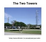
The second cover is a picture I took at a pair of cell towers on the edge of the Everglades swamp. These towers were cranked up to RF emission levels well beyond the typical levels seen in populated areas to cover the Eastern Everglades. Since most of the "population" west of these towers was cattle, goats, and a few horses, nobody complained except the police, since their Motorola radios did not function where I stood to take this picture. The nose of my White 1999 Mustang Convertible can be seen on the right side of the picture.
Note that the term "IM" is the same stuff (InterModulation distortion) that causes chords played through a distorted guitar amp to sound nasty. There, several notes will combine to produce new notes not found in the original chord that are dissident with the original notes of the chord. Power chords are chosen such that their sum, difference, and second order products are consonant with the original notes.
In my RF testing several cell tower signals combined to form intermodulation products that jammed the police radio frequencies that were in the same frequency band as the old Nextel Cellular system. IM distortion is hard to explain without some basic math, but the best and most vivid explanation I gave to a cable TV engineer was that it was the equivalent of tossing all of the TV channels into a blender and pressing the "liquify" button.
With most "textbook" electrical engineering, all electronic systems can be modeled with math and simulated in a computer. This works well in cases where all of the models are well defined, and the system operates within the boundaries defined by the simulation and the math. We would not have the GHz level CPU chips we are using to post these messages without an army of engineers and other skilled experts to define and refine all of that math and simulation stuff. Our research group had over 50 of those simulation and calculation boys, and three of us who built stuff and took it where the models are undefined. BOTH kinds of people are needed to develop NEW technology, or find new applications for old tech.
Just as trying to get a two way radio to work in a mishmash of high level transmission towers where the signal levels FORCE nonlinear operation is outside the boundaries of simulation, so are most guitar amps. Now stick a giant pedal board in front of that guitar amp and set it to a preset called Jimi and simulate that! Sometimes you just have to stick parts together and blow them up.
After one of the usual father-son talks concerning my status as a worthless teenager, I drove 40 miles north and convinced Motorola to hire a kid with no formal electronics education. This was before giving job applicants a written electronics test was deemed discriminatory and banned. They handed me the test and I got the second highest score ever made on that test. After two years in the factory and ten years in the calibration lab I convinced someone to make me an engineer. After I had been an engineer for a while, they sent me to college to collect a degree on their money, TWICE.
Somewhere along the journey I learned the skill of writing a technical report that managers will actually read. Step one is to get their attention and the best place to do that is the front cover. Included are two of mine.
The first shows some testing I did that eventually led to the efficiency improvement mentioned previously but killed a lot of expensive RF power devices and a few ordinary mosfets in the process. The gold colored rectangles are some unique low inductance RF device packages we developed in house for high power transmitters in the 100 MHz to 2 GHz range. Several others and I have collected a few patents on these packages.
The second cover is a picture I took at a pair of cell towers on the edge of the Everglades swamp. These towers were cranked up to RF emission levels well beyond the typical levels seen in populated areas to cover the Eastern Everglades. Since most of the "population" west of these towers was cattle, goats, and a few horses, nobody complained except the police, since their Motorola radios did not function where I stood to take this picture. The nose of my White 1999 Mustang Convertible can be seen on the right side of the picture.
Note that the term "IM" is the same stuff (InterModulation distortion) that causes chords played through a distorted guitar amp to sound nasty. There, several notes will combine to produce new notes not found in the original chord that are dissident with the original notes of the chord. Power chords are chosen such that their sum, difference, and second order products are consonant with the original notes.
In my RF testing several cell tower signals combined to form intermodulation products that jammed the police radio frequencies that were in the same frequency band as the old Nextel Cellular system. IM distortion is hard to explain without some basic math, but the best and most vivid explanation I gave to a cable TV engineer was that it was the equivalent of tossing all of the TV channels into a blender and pressing the "liquify" button.
With most "textbook" electrical engineering, all electronic systems can be modeled with math and simulated in a computer. This works well in cases where all of the models are well defined, and the system operates within the boundaries defined by the simulation and the math. We would not have the GHz level CPU chips we are using to post these messages without an army of engineers and other skilled experts to define and refine all of that math and simulation stuff. Our research group had over 50 of those simulation and calculation boys, and three of us who built stuff and took it where the models are undefined. BOTH kinds of people are needed to develop NEW technology, or find new applications for old tech.
Just as trying to get a two way radio to work in a mishmash of high level transmission towers where the signal levels FORCE nonlinear operation is outside the boundaries of simulation, so are most guitar amps. Now stick a giant pedal board in front of that guitar amp and set it to a preset called Jimi and simulate that! Sometimes you just have to stick parts together and blow them up.
Attachments

I was lucky to have the experience of meeting a fellow when I was in high school, who was a electronic music enthusiast. He built stuff and I wanted to help him out. One time I got him to loan me his ring modulator and phase shifter. It was too bad I didnt play anything at the time, but I managed to connect those to a Whurlitzer piano in the schools band room.
You could set the phase shifter to a static delay time. I fed the piano output direct into one input of the ring modulator, a delayed version into the other input. So now I was listening to something like f(t)*f(t-T), which is just an audio signal multiplied by itself but the other multiplier delayed in time. Made some unusual modulation products; what I distinctly remember was upon playing some ascending scale, I'd get that plus a descending scale along with it. Not necessarily dissonant too, like you'd get from a ring modulator using a constant tone that may not even be a concert musical note. Ala Chick Corea / Jan Hammer used to do.
Then, a few years later I read where in a tube guitar amp, sometimes the speaker can shake the whole chassis including the tubes. Micro-movements of the grids could modulate the electron flow mechanically and what I was reading was claiming that this actually happens when tube amps are played loud and ends up as something you can hear. After loading the pipe, I dreampt up "Well, what if you strung a bunch of guitar strings right across the face of the speaker - like a lyre - tuned them to real notes, had a pickup on each and fed that sum into the modulation input of a ring, or one of those tubes with a 2nd grid, or fet with a second gate"?
I never built it to find out. By then, the ring modulator guy was a few hours away; Motorola was the only place that had a 4 quadrant multiplier at the time and it was $30. Yikes! That would be just to hear what it sounded like; maybe using a second guitar to avoid actually having to build the lyre part. The idea being that as you cranked the volume, those drone strings would start to vibrate and modulate the main signal creating God knows what sound. But only when the amp got loud - like speaker shaking cabinet shaking chassis shaking tubes. If that's actually a legitimate effect -
Unfortunately for me, I've never had a shred of affinity for simulation. I heard in college about a guy using spice to scope out crossovers for speakers, back when we'd hand decks of hollerith cards to the lady operator through a window. Never pursued it. In my employ, I'd run the stuff they'd ask me to, but was never particularly creative with it. That's from the days of fan-fold prinouts of logic signal waveforms with gate input capacitances along a stripline, to several years ago doing voltage drop calculations of some randomly shaped copper planes inside a server PC board with full color CAD results display. Always need to know the damn trick to get it to even digest the input, just that was half the job. I'd debate with other engineers too, who were always after a "better simulator" as the best path to a solution.
Even with the advent of real time audio flowing into a spice simulation and hearing the output, still cant get enough water under my boat to get me much off the beach about it. Lord knows I've had plenty of opportunity to have become some simulation guru by now; instead I liked doing most of my career in automated test programming. At least that had real wires that connected to real things you could pick up and hold.
Last edited:
Throughout my 41 year career at Motorola I rarely used simulation. I did learn the basics of HP / Agilent / Keysight's RF simulator, then called MDS (Microwave Design Software) now called ADS (Analog) since the frequency range was extended down to DC. We were in the process of designing a single hand held walkie talkie that could operate on every frequency that was allocated for public safety (police, fire, EMS, etc) use in the USA which spanned from 136 to 941 MHz, broken into 4 main segments. Now, it really did take an army of experts at "fields and waves" simulation to design one antenna that covers all of the frequencies, but about 6 people in our group were tasked with designing a transmitter for it. Some of the frequencies used by public safety are interspaced with and adjacent to TV broadcast transmitters where up to 1 MEGAWATT of Effective Radiated Power (RF power + antenna gain) is common. This requires very stringent specs for both the transmitter and receiver circuits.
I was credited with "inventing" a circuit I called the triplexer. It connected one antenna to three different receiver circuits, and the same antenna to three different transmitter circuits and made sure that everything went where it was supposed to without RF switching. I "invented" it by directly copying a triplexer from a Yeasu ham radio set (Motorola owned Yeasu at the time) that worked on different ham radio frequencies. I simply stuffed the schematic into ADS and fed a list of my required specs into the ADS optimizer and let it run overnight. When the simulator replied with "cannot converge" or no solution is possible, I made some new guesses at the component values and let it run overnight again. It took about a month, with several weeks of building the real circuit and tweaking it, then simulating again, but it eventually worked and is now used in a product. Simulation does have its place. That place differs from engineer to engineer and with the engineering discipline.
That was my only real useful interaction with a serious simulator that used iterative component value optimization. I still simulate my tube amp ideas in LT spice. I don't put much faith in the simulated distortion numbers, but LT spice is good at finding dumb mistakes or ideas that just won't work. The Saturator used in the guitar amp in post #28 began as an idea in LT spice. The sim showed a predicted maximum gain of over 1000 V/V and that's about what I get with a 2 meg pot turned all the way up. The simulator will not tell you just how microphonic a 18FW6 (18 volt 6AU6) will get at these gain levels. Set the head on the speaker cabinet and there is a point just before the whole thing breaks into a feedback scream where there is this neat glassy sounding reverb effect. The problem is that the more shaking the pentode gets the worse it's microphonics are. Note for next time.....the Saturator needs to be further down the preamp chain, not the input tube.
The Saturator in that amp uses a mosfet for the "gyrator" circuit. Mosfets are off the table in the MetallicAmp (built with 50's and older) parts, but LT spice tells me that a two pentode version will work with a max gain of about 300 to 400 using two 6SJ7's. I haven't built it yet to see if it's real.
One guy retired and I got his simulation he was doing for another engineer. They wanted to quench an overshoot, when some processor pulling 100A let go (finished its task) the Vcc voltage would overshoot too far. So the guy explained to me how his idea worked, but it never really did work, as he was yanking the overshoot back down to ground. Just not a good enough potential difference - like 1.5 - to do much.
As it's "just numbers" it occurred to me that if I increased that potential difference - go to what would be below ground which was an easy change - then the idea started to work pretty good. Unfortunately in a server power system, there aint no negative supply that you could connect it to. It was a given no one was going to add such a thing into the board just so this overshoot quencher could work. There was talk of a patent nonetheless, (the other engineer was quite the IP collector) then we all got involuntarily retired...
Simulation does have its place. Sometimes figuring out what's actually needed for an idea to work.
This afternoon my wife informs me that she was going to bingo night at the local Catholic Church and taking the neighbor next door with her. This means an evening with no limits on excessive volume or weird (synthesizer) sounds. So, what to do? Duh, how about 5 guitars and a bass, two speaker cabinets, and one poor little test amp that's about to get thrashed, hard.
Observations:
My guitar playing has deteriorated much more than I had thought. The arthritis in my left hand started bothering me after about 15 minutes and I had to take a break after about half an hour and quit entirely after a few shorter and shorter sessions since I missed nearly every note after an hour or so.
Oh, you want to hear about the amp, not my whining........OK:
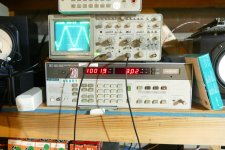
This afternoon I swapped out the power transformer for one salvaged from a HP audio oscillator. This brought the idle B+ down to about 380 volts with the preamp connected. Idle dissipation was still high at about 18 watts on the worse tube. The "shot in the dark" photos reveal a dim glow in the plate on that tube. They also reveal some glowing grid wires on the tube with the lowest idle dissipation. I think I may have partially zapped that tube early on when the plate lead from the OPT came loose while the amp was powered up. The screen grid had to eat a lot of power that should have gone to the plate for as long as it took me to hit the KILL switch, about 1 second. There was a bright glow from inside the tube during that time. It still works well enough, so it stays in the amp until I get the dissipation down further.
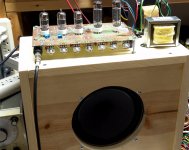
Upon first power up of the combined preamp and power amp I was met with some oscillation. I remembered the same kind of stuff on a guitar amp I designed and built for the Hundred Buck Amp Challenge (pictured on top of a pine board speaker cabinet), and how I fixed it. All of the pot cases must be grounded. Finding that 12 year old picture got me thinking about what happened to that amp. There were two nearly identical boards that only differed in the choice of output tubes. The octal output board used sweep tubes and never really worked right. It lives in the box of dead circuits, but the 9 pin board was not there. A few hours later I remembered building a case for it. It is the amp on the bottom of the pile in post #1 that "just needs an OPT." It had been sleeping in a box on a shelf for 12 years. It is already out of its box and a suitable OPT is being installed. It will be revisited soon.
After running a thin wire to all of the pots it appeared that everything was ready, so I hooked up the smaller speaker cabinet, and plugged in the red Strat. As soon as the cord hit the jack the feedback started. This thing has WAY TOO MUCH GAIN. There are four volume pots counting the one on the guitar. Best clean tone is found with the guitar's volume at about 5 (1 to 10 knob) and the input gain (between stage 1 and 2) barely cracked, maybe 1/2 on the 1 to 10 scale. The second pot can be turned one way to bypass the second stage, the other way to use all of the second stage's gain, or somewhere in between for partial cancellation between the two stages. I prefer a setting that uses just a bit of the second stage gain, nearly full cancellation. Even at this setting the Master Volume can't be turned past 5 without driving the power amp to full saturation (square waves with ringing on the scope across the speaker). It is possible to get some really nice clean tones with careful adjustment of the pots and the amp can be turned up quite loud with the MV before distortion sets in, feedback happens first even with the speaker pointed away. Any setting past about two or three on the input gain caused blocking distortion in the preamp! Dime the knob, hit a string, and silence happens for up to a second. It's definitely happening in the preamp since it can be seen on the scope at the preamp / amp connection, but I didn't dig deeper yet. Settings slightly above one does generate some nice, distorted tones, but things are far to touchy.
I ran through all of the guitars. The Guild has DiMarzio humbuckers from the early 70's they put out more signal than any of the other guitars, so it's hard to find a clean setting, but sounds great when you do. The Les Paul is the other extreme. I got the big 40 pound speaker off the shelf for that one, as that heavy brick of a guitar is less prone to feedback than the others. The Les Paul / big speaker cabinet combo is really good for loud clean tones......too loud to be near it kinda loud. Of course, I had to crank some surf sounds from the Univox that I have owned for nearly 50 years, but I REALLY need some reverb for that stuff. Again this setup can go REALLY loud since the EV speakers are about 8 db more efficient than the Parts Express cheapies. The amp still hits over 40 watts even with the smaller power transformer. Lastly I had to try it with a bass. I was pleasantly surprised that it sounded good, and didn't blow up even when pushed to near clipping. Tweaking the tone controls can get some near perfect sine waves across the speaker, somewhat unusual for a guitar.
There had been this background hiss which got louder as the night progressed and began to sound like bacon frying after playing the bass loudly shook up the whole workbench. Poking around in the power amp with a plastic tool made it go away, but a minute or two with the bass brought it back. Wiggling one of the output tubes revealed the source, so all 4 tubes got their pins cleaned with a toothbrush and WD40. Problem solved.
I plan to experiment with some gain reduction in the near future, but first I'm going to fire up a guitar amp I built 12 years ago and see if it goes or blows!
Observations:
My guitar playing has deteriorated much more than I had thought. The arthritis in my left hand started bothering me after about 15 minutes and I had to take a break after about half an hour and quit entirely after a few shorter and shorter sessions since I missed nearly every note after an hour or so.
Oh, you want to hear about the amp, not my whining........OK:
This afternoon I swapped out the power transformer for one salvaged from a HP audio oscillator. This brought the idle B+ down to about 380 volts with the preamp connected. Idle dissipation was still high at about 18 watts on the worse tube. The "shot in the dark" photos reveal a dim glow in the plate on that tube. They also reveal some glowing grid wires on the tube with the lowest idle dissipation. I think I may have partially zapped that tube early on when the plate lead from the OPT came loose while the amp was powered up. The screen grid had to eat a lot of power that should have gone to the plate for as long as it took me to hit the KILL switch, about 1 second. There was a bright glow from inside the tube during that time. It still works well enough, so it stays in the amp until I get the dissipation down further.
Upon first power up of the combined preamp and power amp I was met with some oscillation. I remembered the same kind of stuff on a guitar amp I designed and built for the Hundred Buck Amp Challenge (pictured on top of a pine board speaker cabinet), and how I fixed it. All of the pot cases must be grounded. Finding that 12 year old picture got me thinking about what happened to that amp. There were two nearly identical boards that only differed in the choice of output tubes. The octal output board used sweep tubes and never really worked right. It lives in the box of dead circuits, but the 9 pin board was not there. A few hours later I remembered building a case for it. It is the amp on the bottom of the pile in post #1 that "just needs an OPT." It had been sleeping in a box on a shelf for 12 years. It is already out of its box and a suitable OPT is being installed. It will be revisited soon.
After running a thin wire to all of the pots it appeared that everything was ready, so I hooked up the smaller speaker cabinet, and plugged in the red Strat. As soon as the cord hit the jack the feedback started. This thing has WAY TOO MUCH GAIN. There are four volume pots counting the one on the guitar. Best clean tone is found with the guitar's volume at about 5 (1 to 10 knob) and the input gain (between stage 1 and 2) barely cracked, maybe 1/2 on the 1 to 10 scale. The second pot can be turned one way to bypass the second stage, the other way to use all of the second stage's gain, or somewhere in between for partial cancellation between the two stages. I prefer a setting that uses just a bit of the second stage gain, nearly full cancellation. Even at this setting the Master Volume can't be turned past 5 without driving the power amp to full saturation (square waves with ringing on the scope across the speaker). It is possible to get some really nice clean tones with careful adjustment of the pots and the amp can be turned up quite loud with the MV before distortion sets in, feedback happens first even with the speaker pointed away. Any setting past about two or three on the input gain caused blocking distortion in the preamp! Dime the knob, hit a string, and silence happens for up to a second. It's definitely happening in the preamp since it can be seen on the scope at the preamp / amp connection, but I didn't dig deeper yet. Settings slightly above one does generate some nice, distorted tones, but things are far to touchy.
I ran through all of the guitars. The Guild has DiMarzio humbuckers from the early 70's they put out more signal than any of the other guitars, so it's hard to find a clean setting, but sounds great when you do. The Les Paul is the other extreme. I got the big 40 pound speaker off the shelf for that one, as that heavy brick of a guitar is less prone to feedback than the others. The Les Paul / big speaker cabinet combo is really good for loud clean tones......too loud to be near it kinda loud. Of course, I had to crank some surf sounds from the Univox that I have owned for nearly 50 years, but I REALLY need some reverb for that stuff. Again this setup can go REALLY loud since the EV speakers are about 8 db more efficient than the Parts Express cheapies. The amp still hits over 40 watts even with the smaller power transformer. Lastly I had to try it with a bass. I was pleasantly surprised that it sounded good, and didn't blow up even when pushed to near clipping. Tweaking the tone controls can get some near perfect sine waves across the speaker, somewhat unusual for a guitar.
There had been this background hiss which got louder as the night progressed and began to sound like bacon frying after playing the bass loudly shook up the whole workbench. Poking around in the power amp with a plastic tool made it go away, but a minute or two with the bass brought it back. Wiggling one of the output tubes revealed the source, so all 4 tubes got their pins cleaned with a toothbrush and WD40. Problem solved.
I plan to experiment with some gain reduction in the near future, but first I'm going to fire up a guitar amp I built 12 years ago and see if it goes or blows!
Attachments


Sounds like my kind of evening!
Although I don't play any instrument, my son is a musician and has better ears for music than I have. A few years back, I moved one of my stereo systems to another room and was playing some LPs. He said it didn't sound right, like it was out of phase. I checked the speaker connections and sure enough, one of the speaker connections had the polarities reversed.
I moved all my gear into the garage, except for the HT system. My wife and son never liked my music selection or the volume. I used to live near the Rose Bowl in Pasadena, CA. I loved game days or concerts because no one could complain about the volume or music selection and it sometimes got very loud...
Second photo is what's left after retiring and moving back to NM. I gave away or sold most of my other gear. I look forward to playing it loud when my wife goes out shopping or visits friends.
Attachments


As far as recommending a reverb amp for the surf clank and drip.
Or pretty much anything.
Usually the Vintage Fender Vibroverb.
2 channel with 6L6 pair tremolo and reverb.
Pretty intense build with 2 channels.
Most people jump to modding it to be One Channel
and go from 6L6 to 6V6 for less power.
No need to re invent the wheel, whatever " custom" Fender
you think of Leo likely already did it.
Usually Resort to the ever so classic Princeton Reverb.
1 channel Reverb/ Tremolo 6V6 output, then use 1x12 cabinet
It is basically the slimmed down version of the Vibroverb
that people imagine.
And the transformers and tanks dont need guesswork
since Fender iron and tank replacements are very much available
Vibroverb
Princeton Reverb
The usual canidates for magic with the Princeton
is phase splitter is different simple cathodyne. 6V6 outputs
and Tube Rec in the power supply. So the breakup is rather
well known classic. Trem is the bias trem which many " pedals"
try to emulate. Reverb is the other classic design when the switched
to using both sides of a 12AU7 to drive the tank. Easier transformer
and not larger bottle. the classic fender reverb sound.
people have modded to use stock 2 spring smaller tanks, or use the larger 4 spring tanks
from the Twin Reverb
Last edited:
I have built plenty of Fender clones in my lifetime including the Princeton Reverb with a pair of 6V6GT's. I have tended toward exploring different path since then.
I have a few reverb tanks suitable for guitar amps, a Belton digital reverb unit, a DIY board with a Spin FV-1 (I think) FX chip on it and there are bunches of reverb tanks in stock at AES for reasonable prices, so I have multiple choices for reverbs. Back in my high school days I had a 30 inch reverb tank from a Hammond organ that I drove with a little solid state amp and I just plugged its output into one of the channels on my guitar amp. All of that fun stuff was lost when I left home under less than ideal circumstances. I have since scored a similar tank on Ebay and it does work, so that will work its way into my synth rack sooner or later.
Last night after playing with the test amp and a bunch of guitars, I decided to plug in the 12 year old amp and see what happens. There was some parts and wiring missing, as well as some memory lost as to exactly what I had done and why. I have vivid memories of building three amps for the Hundred Buck Amp Challenge. One was a simple 4 tube 4 watt amp built for absolute minimum parts cost (about $45 in 2011) to squelch the guy that started the challenge in the first place.
See post #12 and #14 here if interested:
https://www.diyaudio.com/community/threads/need-recommendations-for-diy-small-guitar-amp.190449/
There were two other amps created to see just could be made for $99.99 of less. The 5 tube amp seen sitting on the speaker cabinet in the first picture seen in post #36 just squeezed in under $100 in 2011. Most of my memories involve working on that board, and the other two, while it sat on top of that speaker cabinet. At any given time I had several experiments in process on my workbench. During the course of the HBAC it became obvious that my engineering career at Motorola was on life support as the Wall Street Wizards had bought into the company and were in the process of busting it up and parting it out like a junk car. I had watched the same people break up and sell off three airlines based out of Miami, so I had assumed the end was near. I started down the road to retirement and put my house up for sale, for more than it was worth. I had an orderly plan to move everything to my retirement location little by little with rented trucks in 4 trips. We were unloading the first truck when my house sold, and we had 3 weeks to move out. Panic ensued and stuff got lost.
I had several projects underway before the exit, including some speaker cabinet builds. digging through the pictures on my hard drive, It seems that along with some FH-3 and EZ-10 horn speakers, a few amp cabinets were made. The picture of me at the table saw shows both the original 4 tube amp and the bigger 5 tube amp chassis on the ground to the left of the saw. It also shows three cabinets. I can only find two of them. Is there another amp somewhere that I can't find.
It seems that I had been looking for this amp off and on, but remembered it as being a bare PC board with two transformers hanging off of it. Once relocated to my retirement house I began to dig through the boxes that got stashed into an abandoned mobile home on our property that is now just used for storage. It was found and discussed in post #2064 and 2065 here:
https://www.diyaudio.com/community/threads/the-hundred-buck-amp-challenge.190738/page-104
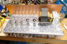
I completed the wiring for the power transformer and mounted a real guitar amp OPT identical to the one that I have been using so far in this thread in the holes that were already drilled in the chassis. The holes were drilled a long time ago as they are visible in some of the backyard pictures. Upon power up, nothing happened. The tubes glowed but there was no sound at all in the speaker until I plugged in a guitar cable. This thing is quiet, but works very well. It's not as loud as the test amp, but sounds much nicer in both clean and cranked operation.
there is obvious evidence that I have hacked on this amp, but so far I can find no documentation as to what I did, or when I did it. There is some cut traces and flying parts under the deck. I don't believe that it has been powered up since it landed in a box in Florida since there was no OPT. The Antek power toroid had been mounted, which was the magic part that was required to meet the budget. Its wires had never been cut or soldered. I ripped it out and installed a real OPT that worked better in original (2011) testing.
I have a few reverb tanks suitable for guitar amps, a Belton digital reverb unit, a DIY board with a Spin FV-1 (I think) FX chip on it and there are bunches of reverb tanks in stock at AES for reasonable prices, so I have multiple choices for reverbs. Back in my high school days I had a 30 inch reverb tank from a Hammond organ that I drove with a little solid state amp and I just plugged its output into one of the channels on my guitar amp. All of that fun stuff was lost when I left home under less than ideal circumstances. I have since scored a similar tank on Ebay and it does work, so that will work its way into my synth rack sooner or later.
Last night after playing with the test amp and a bunch of guitars, I decided to plug in the 12 year old amp and see what happens. There was some parts and wiring missing, as well as some memory lost as to exactly what I had done and why. I have vivid memories of building three amps for the Hundred Buck Amp Challenge. One was a simple 4 tube 4 watt amp built for absolute minimum parts cost (about $45 in 2011) to squelch the guy that started the challenge in the first place.
See post #12 and #14 here if interested:
https://www.diyaudio.com/community/threads/need-recommendations-for-diy-small-guitar-amp.190449/
There were two other amps created to see just could be made for $99.99 of less. The 5 tube amp seen sitting on the speaker cabinet in the first picture seen in post #36 just squeezed in under $100 in 2011. Most of my memories involve working on that board, and the other two, while it sat on top of that speaker cabinet. At any given time I had several experiments in process on my workbench. During the course of the HBAC it became obvious that my engineering career at Motorola was on life support as the Wall Street Wizards had bought into the company and were in the process of busting it up and parting it out like a junk car. I had watched the same people break up and sell off three airlines based out of Miami, so I had assumed the end was near. I started down the road to retirement and put my house up for sale, for more than it was worth. I had an orderly plan to move everything to my retirement location little by little with rented trucks in 4 trips. We were unloading the first truck when my house sold, and we had 3 weeks to move out. Panic ensued and stuff got lost.
I had several projects underway before the exit, including some speaker cabinet builds. digging through the pictures on my hard drive, It seems that along with some FH-3 and EZ-10 horn speakers, a few amp cabinets were made. The picture of me at the table saw shows both the original 4 tube amp and the bigger 5 tube amp chassis on the ground to the left of the saw. It also shows three cabinets. I can only find two of them. Is there another amp somewhere that I can't find.
It seems that I had been looking for this amp off and on, but remembered it as being a bare PC board with two transformers hanging off of it. Once relocated to my retirement house I began to dig through the boxes that got stashed into an abandoned mobile home on our property that is now just used for storage. It was found and discussed in post #2064 and 2065 here:
https://www.diyaudio.com/community/threads/the-hundred-buck-amp-challenge.190738/page-104
I completed the wiring for the power transformer and mounted a real guitar amp OPT identical to the one that I have been using so far in this thread in the holes that were already drilled in the chassis. The holes were drilled a long time ago as they are visible in some of the backyard pictures. Upon power up, nothing happened. The tubes glowed but there was no sound at all in the speaker until I plugged in a guitar cable. This thing is quiet, but works very well. It's not as loud as the test amp, but sounds much nicer in both clean and cranked operation.
there is obvious evidence that I have hacked on this amp, but so far I can find no documentation as to what I did, or when I did it. There is some cut traces and flying parts under the deck. I don't believe that it has been powered up since it landed in a box in Florida since there was no OPT. The Antek power toroid had been mounted, which was the magic part that was required to meet the budget. Its wires had never been cut or soldered. I ripped it out and installed a real OPT that worked better in original (2011) testing.
Attachments


Well, I've only read down part way but the first thing that popped into my mind when seeing the welcome mat was "What about those big Plitrons?"Any and all ideas are welcome.
'Guess I'd better keep reading .
- Home
- Live Sound
- Instruments and Amps
- Tubelab wants a new guitar amp