In between the wind and rain, the "screw-up" box has been modified such that the Eminence 12 inch speaker should fit. It has been assembled without the driver and has 1 complete coat of Duratex painted onto it. I have not ripped the guts out of the box that Tone Test amp lives in so that it can be painted with the same stuff. 100% chance of rain for 100% of the useful daytime working hours says that nothing will be done to either cabinet tomorrow.
I have been investigating the breadboarding of several circuit concepts and while digging through a box labeled "prototyping materials" I found two interesting relics from my past.
The PC board was designed by another forum member specifically for use with the European D3A tube in HiFi applications. It is capable of running in triode or pentode mode and can be configured for a few of the common topologies of the time. The date on the boards read 2009, 14 years ago. The D3A will never be seen in a guitar amp due to its scarcity and price. The schematic and build info for these should be on a hard drive of mine somewhere, but I have not yet found it. The web site it was on is no longer up, and the Wayback Machine can't find it. Something similar could be made for tubes that I would consider using.
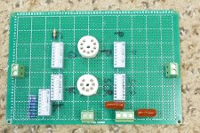
The perf-board creation has a 7 pin socket and a 9 pin socket with like number pins wired in parallel. Each pin is also wired to the like numbered pin on 4 different switches, Cathode, G1, G2 and plate. A fifth switch allows for several different cathode resistors one at a time, or in combination. This one looks like it was never finished. There should also be an octal version that was completed with switchable plate resistors. The last time I saw it was in Florida with a 6SJ7 stuck in it.
There was also a thread here about some single stage boards made specifically for guitar amp use. A box full of all the popular topologies would be cool, but they went extinct a while back. Again something similar can be made.
https://www.diyaudio.com/community/threads/valve-wizard-experimental-pcbs.408565/#post-7600181
In reality, I am looking into rolling my own test boards that would be like the "best of" all three concepts.
I have something I call the UNSET Power Head board that is just two UNSET output stages with octal sockets (seen here showing off some nice metal 6L6 tubes). I have been using them with various driver circuits in both HiFi and guitar applications. I just finished a layout for the same thing with 12 pin Compactron sockets. I may do a "mini" version for 7 or 9 pin tubes.
I have been investigating the breadboarding of several circuit concepts and while digging through a box labeled "prototyping materials" I found two interesting relics from my past.
The PC board was designed by another forum member specifically for use with the European D3A tube in HiFi applications. It is capable of running in triode or pentode mode and can be configured for a few of the common topologies of the time. The date on the boards read 2009, 14 years ago. The D3A will never be seen in a guitar amp due to its scarcity and price. The schematic and build info for these should be on a hard drive of mine somewhere, but I have not yet found it. The web site it was on is no longer up, and the Wayback Machine can't find it. Something similar could be made for tubes that I would consider using.
The perf-board creation has a 7 pin socket and a 9 pin socket with like number pins wired in parallel. Each pin is also wired to the like numbered pin on 4 different switches, Cathode, G1, G2 and plate. A fifth switch allows for several different cathode resistors one at a time, or in combination. This one looks like it was never finished. There should also be an octal version that was completed with switchable plate resistors. The last time I saw it was in Florida with a 6SJ7 stuck in it.
There was also a thread here about some single stage boards made specifically for guitar amp use. A box full of all the popular topologies would be cool, but they went extinct a while back. Again something similar can be made.
https://www.diyaudio.com/community/threads/valve-wizard-experimental-pcbs.408565/#post-7600181
In reality, I am looking into rolling my own test boards that would be like the "best of" all three concepts.
I have something I call the UNSET Power Head board that is just two UNSET output stages with octal sockets (seen here showing off some nice metal 6L6 tubes). I have been using them with various driver circuits in both HiFi and guitar applications. I just finished a layout for the same thing with 12 pin Compactron sockets. I may do a "mini" version for 7 or 9 pin tubes.
Attachments


It is to wonder if something could be done along the lines of https://www.seymourduncan.com/blog/latest-updates/the-100-watt-guitar-ampI just finished a layout for the same thing with 12 pin Compactron sockets. I may do a "mini" version for 7 or 9 pin tubes.
Not the 100W part, but some sort of socket / tube carrier that'd fit into a common pin field on the main PCB. Perhaps it's just too much work to manage several card layouts. That would get your asymmetrical output stage perhaps more into the realm of a reasonable thing to do, versus just direct socket adapters.
All of my Seymour Duncan stuff lives on the front of a guitar. I never realized that they made amps. These came from a time period when I made very few guitar amps and they were all solid state. Most used clones of one of the SWTPC Tiger amps for the power amp and preamp circuitry based on several amps (Acoustic, Kustom, etc) that I traced out when fixing them for friends. From the early 70's through the 90's I had a Kustom K-200 that I resurrected from the (seriously) dead after the amp tech at Ace Music in Miami pronounced it unrepairable. Somewhere in the liner notes of the first Chicago Transit Authority albums is a description of how Terry Kath created the sound on Free Form Guitar. It involved using a Bogen PA amp as a preamp for his regular guitar amp. That may work if the guitar amp is a tube amp, but cramming 35 watts of energy from a vacuum tube Bogen PA amp operating without any load into the input jack on a solid state Kustom blows parts, LOTS of parts. I wound up simply changing all of the silicon in the preamp stages and a few shorted electrolytics before I could get reasonable DC voltage readings. The output stage in all the early Kustoms was copied verbatim from the RCA transistor manual, as was the Heathkit guitar amp.
Some Googling brought me a couple manuals and a schematic or two, but no pictures of exactly how the modules mount into the amp and can be swapped, except a text based narrative that includes the wording that some modules must be tilted or rotated to clear the opening.
Some Googling brought me a couple manuals and a schematic or two, but no pictures of exactly how the modules mount into the amp and can be swapped, except a text based narrative that includes the wording that some modules must be tilted or rotated to clear the opening.
I think they used some kind of card edge connector, probably borrowing from the old DEC "flip-chip" plug in computer cards. Not suggesting that's the way to go for an output tube daughter card; I just somehow vaguely recall a picture of one the of modules with a card edge connector row fab'd in printed circuit form.exactly how the modules mount into the amp and can be swapped
It's an interesting idea (cold swap-able elements) and I'm amazed you can still buy the product; I'd figured, like so many things, it would have faded all the way into obscurity - as perhaps no one besides Jeff Beck liked it and even he's gone now.
After watching every video the guy had on the SD Convertible, and studying every schematic, I realize that this thing was a great exercise in clever marketing. The core design of most of the modules is the typical two stages of 12AX7 stuff. The differences between about 5 of them comes down to capacitor and resistor values.
I spent several years in product design at Motorola doing "mission critical" two way radio design for public safety (police, fire...) use. Here someone's life may depend on that radio working correctly. From the early 80's through the late 90's we examined every possible failure mechanism in every radio design we made and assigned weights to each of them in order to work on the biggest issues first. Most of the big hitters were related to controls and connectors. Eliminating every connector in the product that didn't absolutely need to be there greatly improved product reliability, especially when the unit received some physical abuse. Do guitar amps get banged around and have to eat their own sources of vibration? The modular guitar amp was a neat idea in its time, but I'll use a more conventional approach.
I also spent about 4 years in cell phone design where we studied things like how much does it cost us to place a part on an automated pick and place line? These things are what matters when your run rate is 1 million units a month! Connectors cost real money, so they needed to go!
I'd have to guess they marketed to the wrong set of individuals. Seems susceptible to the "lost remote control" effect, where the next time you go to use it; "where's my high gain forward presence module - it was in my cord box last time I looked". Plus the reliability issues you mention, all those connectors contact fretting as the thing get transported around.I realize that this thing was a great exercise in clever marketing.
One engineer told me they did a vibration test on a crimped vs soldered connection. Said the soldered one failed every time.
Thanks for posting the video! Interesting.
I was following some links related to the Convertible when I found myself on a guitar amp forum that I never heard of, in a thread about the Convertible. It seems that those who still use one of these gigging will not forget their trusty contact cleaner spay and Q-tips even if they are not swapping modules.
Somewhere in my wandering the internet today I grabbed this picture. The modules use the PC board itself for a 6 pin connection into a card edge connector. After some time the plating wears thin and connections go intermittent. the average amp tech will simply flow some solder over what's left of the copper pad. If you have ever done this, you will know how long it lasts.
In the 70's I was part of a group of people at Motorola that built home computers. There were two dominant bus standards then. The S-100 bus used Intel or Zilog 8 bit processors on boards that featured 100 pins made the same way the connectors in the Convertible were. The SS-50 buss from SWTPC (the same people who did the Tiger series of solid state amps) used a Motorola 8 bit chip that ran at a blazing 921 KHz. The connectors were made by Molex. They was a male row of thick pins that went on the motherboard, and a matching socket that fit on the plug in cards. Granted, we lived in hot and humid south Florida, but many of those S-100 machines were intermittent and flakey after about two years of use. My SWTPC machine was still beeping out 8 bit "chiptune" music when I gave it to a museum in the 90's. It should be noted that IBM DID make the card edge thing work with the original PC, and they did it in Florida about 14 miles from my house.
I still have a box full of those SS-50 Molex connectors should I choose to make some plug in test boards.
Attachments

Although I'm no connector expert, I do know enough that if you're willing to pay $, you can get pretty good ones. It seems Seymour wanted to spend the least on that part of their idea as possible, by cutting the expense down by 1/2 - just etch one half into the PCB you're already making and you dont have to spend anything for a mating component.
There's not so many pins either; we did solder "Bananna" plugs directly to a PCB edge on test boards, to a pad where at least some thought was put - PTHs and strapping wires. That would make the Seymour modules a bit wider, but 4 "wipes" per signal are better than 1 - out of a very common / simple part like a bananna jack.
Interesting they knew of the paralleling triode as sonic ingredient, versus some other topology they could have done with two stages.
Did you glean any details on their special power supply? Anything there any good? I once had an HH Scott "Laboratory Power" amp with an output power dial - but all that did was shutdown the amp in a fairly gruesome way (6080 pass tube would red plate) whenever the set power limit was touched. I pulled the 6080 and just jumped the B+ past that circuit. Hey, that was 40 years ago, when McGee radio was still in business...
I have to say, one time a friend brought me a pair of those HH Scotts to repair, when I was in High School. I could not make them work, no matter how I tried, so he took them to a shop. Later I asked how did they fix them. He said they replaced the input potentiometers! Pissed me off...I've never been the sharpest tool in the shed.
I bought the C3M 20V version of the D3A, Read that the heater does not like being all shook up. Would be nice running it in pentode or triode in the first stage. Maybe as a head.The PC board was designed by another forum member specifically for use with the European D3A tube in HiFi applications. It is capable of running in triode or pentode mode and can be configured for a few of the common topologies of the time. The date on the boards read 2009, 14 years ago. The D3A will never be seen in a guitar amp due to its scarcity and price. The schematic and build info for these should be on a hard drive of mine somewhere, but I have not yet found it. The web site it was on is no longer up, and the Wayback Machine can't find it. Something similar could be made for tubes that I would consider using.
I looked up the going prices for both tubes and was quite surprised. I got my pair of D3As when I got the test boards which was in 2009. I think they cost me about $40 total including shipping from Germany. Seeing what they go for now makes me want to sell them.
I plan to use one of the TV IF amp pentodes that's pin compatible with the 6EJ7/EF184. I have a bunch of them, some 6JC6's, 6JD6's, 6EH7's, and several hundred "counterfeit" 6KT6's. They are all cheap, and I think that I can hack the old D3A test boards to run them.
There is a little (5 X 5 X 10 inch) guitar amp head (the one in the black case) seen in the first picture in post #1of this thread. It uses a 18FW6 pentode (18 volt 6AU6) for the first gain stage which has variable gain up to nearly 1000 V/V. That feeds a tone stack which feeds a 18FY6 triode (like a 6 volt triode from a 12AX7) that drives the mosfet PI. The little amp only makes 4 watts cranked but leaving the head on top of the speaker box will rattle the high gain pentode stage until it does become microphonic. Before I get too far down this guitar amp build, I'm going to crack it open as I need to make a new faceplate for it anyway and hack a few traces to swap the triode and pentode stages.
When I get back to it I will be using a 5654W (ruggedized 6AK5) for the front end of a small combo using a 8" speaker. Hoping it does not feed back too much. I built a sort-of Bassman with 12AB5's with a Fender speaker out of a Blues Jr (I think) and a 12AU6 up front. Don't turn it up all the way at volume. Forgot how loud stage volumes were.
I forgot about those little guys (the 6AK5). Maybe the small size will calm the microphonics. I just looked in my stash and I have 10 new ones in the box, and I know there is a bag full of used ones in the shed. I'll have to hook one up. You reminded me that I built a tiny 5C1 champ with a 6AK5 driving a 6AK6 maybe 20 years ago. It was small enough to fit into the spring cavity of a Strat, without the springs of course. A quick look at my vacuum tube spreadsheet shows that there are over 40 tubes that are pin compatible with the 6AK5 as long as you connect pins 2 and 7 together at the socket.

Tubelab presents the DEAFSTAR 20000 a total shreadmaster of an amp with 20,000 MIGHTY MILLIWATTS of ear splitting POWER!
Now, back to reality this is the board called ToneTest seen in post#36 that got stuffed into a cabinet in post $39. I slapped two coats of Duratex on the old cabinet after it met the belt sander this afternoon while coating the speaker box that I built over the last few days. Outdoor work time has been splintered by high winds and freezing temps, or rain.
Reality showed its ugly head while playing this thing with the head sitting on top of the speaker box. Like the old ADA MP-1 there are some intermittent issues and a persistent distortion that comes and goes with no apparent cause or pattern. I may, or may not dig into it in search of the cure. All of the pots are also intermittent. I abandoned this thing 10 years ago for a reason, I just don't remember what it was.
I now have a 12 inch Eminence guitar speaker in a box. It does sound nice, clean, and loud, so I'll hook the 4 X EL84 stuff back up when I get a chance.
Attachments


The weather held up today so I worked outside all day cutting up and burning a couple dead trees and working on a bigger speaker box for guitar amp use. This one named the "Earschplittenloudenboomer" will have a 15 inch speaker and a pair of 6 inch speakers and be setup for biamplification.
I had the cabinet sitting in the middle of a three year old picnic table on our driveway and I was sitting on one of the benches painting the cabinet with "Tolex" in a can. I was about halfway done with the first of two coats when there was a loud crack and I found myself on my back with the speaker cabinet on top of me. The back of my head had collided with the asphalt pretty hard and my right leg was covered in blood. The speaker box work ended abruptly. I took these pictures with my phone about an hour later.
I had the cabinet sitting in the middle of a three year old picnic table on our driveway and I was sitting on one of the benches painting the cabinet with "Tolex" in a can. I was about halfway done with the first of two coats when there was a loud crack and I found myself on my back with the speaker cabinet on top of me. The back of my head had collided with the asphalt pretty hard and my right leg was covered in blood. The speaker box work ended abruptly. I took these pictures with my phone about an hour later.
Attachments


Holy cow, man! The older we get the less good we tend to be at responding to physical surprises, including keeping balance during a fall. Also, the older we get the longer it takes recover from a fall or other damage. My ex was found a couple of months ago unconscious on the ground in her flat. She apparently hit her head as she fell for some unknown reason, which then ended up with her spending 10-days in the hospital as a result. Just found out about that recently. Hope you are mending okay after your incident.
Ohch. I hope you're watching for concussion symptoms and there arent any. I'd flood those skin abrasions with neosporin, if they were on mine. Reminds me a little of when I pulled a big six channel amp off the bench onto my leg, as I passed out standing there (which I attribute to a c-vid shot taken earlier that day). I wasnt walking OK afterward - forget jogging for the rest of that year. Take care!The back of my head had collided with the asphalt pretty hard
Some time ago I bought a 4 channel tube amp, Motorola console origin. Two 6V6 P-P, two 6V6 SE. Was wondering if driving 4 guitar speakers with it would work out. What would make it interesting would be if a small delay, amp to amp would give the whole thing a very fat sound. According to Tom Scholz, he answered the "what makes several Marshall stacks sound that way" question in his Rockman product by mixing several delayed signals together.
I have no idea what to use to effect, say, 3 short delays - these days. Maybe 3 cheap Donner pedals. The little SEs would "come on first" like the octave string on a downstroked 12 string - the bigger P-P amps / speakers would sound "behind" them. Or maybe it's the other way around.
Tubey,
Ouch! I do hope you don’t have any long term issues.
I don’t recognize the wood used. For the broken piece I normally expect that to be a 2x6. However I can only suspect prior damage must have started the split.
The only good news is that the bench didn’t fail on a load of three or four people!
My wishes for a speedy recovery.
ES
I was wandering a large flea market near my home in Florida back in the 1990's when I spotted a fairly large combo style guitar amp with 4 octal tubes and a five 9 pin tubes in the back. The seller kept saying "tu-bamplifier, it work, mon, $50." I was about to give him the money when I attempted to pick it up. Realizing that I would have to carry it to my car which was nearly a mile away and on the other side of a 6 lane road I decided to pass. When the seller dropped the price to $35, I picked up the amp and started walking. I was a much more muscular guy then than I am now, but it still took me over an hour to get that amp to my car.
The amp was a "Panoramic UltraFlex" made by the Audio Crafters Guild in 1960. I have seen the same amp branded Magnatone. It is very rare. It did indeed work and had a unique design which provided a sound that I could not find anywhere else. I played it daily for many years. The amp had two preamps, with the usual two inputs, and a third jack that fed both channels at the same time. This is fairly common today. In most amps the channels are summed and fed to a common power amp. In this amp the summed channels are fed to the "Ultraflex Balance" control which fed two different power amps, each connected to its own speaker. The two amps both used the same output tubes, but were not the identical, as one was voiced for low frequencies, and the other, highs, note that the two OPT's are different sizes. The speakers were two different sizes. 12 inch and 8 inch.
When I had to leave Florida on three weeks notice after living in the same house for 37 years, I wound up giving the amp to another forum member, and never saw it again. The unusual speaker cabinet I am making will be used (with a few dings built in) for my attempt to recreate the sound that the old amp made. An identical amp can be seen here:
https://reverb.com/item/36075502-vintage-1960s-audio-guild-panaramic-ultraflex-magnatone
The picnic table was bought at Lowes 2 or 3 years ago. They had lots of them already assembled in their parking lot for $99 each. The wood is typical Florida / Georgia Yellow Pine, the same stuff I am making the speaker cabinet out of. My first thought after I recovered my senses was "why did they drill the two bolt holes in line with each other and the grain of the wood." it also looks like some wood rot had started around the outermost bolt hole.
My back, shoulders and right leg are quite sore today and there is a mild lump on the back of my head, but there doesn't seem to be any long term effects so far. I put gobs of Mupirocin on the leg wounds. It is an antibiotic ointment that the doctor prescribed for me since I'm always poking holes in my body in some unintended manner.
- Home
- Live Sound
- Instruments and Amps
- Tubelab wants a new guitar amp