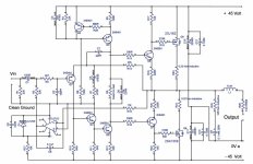
I'm going to say no although a lot depends on your rail voltage. Collector dissipation is the issue @300 mW maximum. On -/+45 volt rails they see around 270 mW dissipation and that changes instantaneously with signal. Worst case they can see instantaneous values of around 500 mW.
The 2SA970 should be OK for the input transistor though.
Are 2SA1208 and 2SC2910 still available, they might be suitable.
What is everyone else who has built this using these days?
The 2SA970 should be OK for the input transistor though.
Are 2SA1208 and 2SC2910 still available, they might be suitable.
What is everyone else who has built this using these days?
It's good for 3.2A. On single die devices, That's pretty much the same as the fuse you're likely to be using. Under normal use you won't pull anything like that. As you say, it isn't difficult to beef those traces up with solid copper wire.@geoffw1,
It’s a good thing I use my amplifiers domestically, not foreign.
I could always add a p2p piece of solid core copper wire to “beef up” the traces.
To confirm,
The inductor on the output is in series with the 0.22R resistor rather than in parallel with the inductor as one typically finds at the output of SS amplifiers?
If so I need to order some new pcbs....
Also my coils have ended up at approximately 4.5uH. Do I need to make a new set of coils or will this be close enough?
What size wire did other people use for their output inductors?
Last edited:
Yes, but: there's another one with 10 ohms in parallel with the inductor. Do not omit that one! The single, series-0.22R may be omitted if you have the inductor//10R in place.The inductor on the output is in series with the 0.22R resistor rather than in parallel with the inductor as one typically finds at the output of SS amplifiers?
4.5H is fine. I did not bother measuring the inductance of my coils at all (they're probably much lower in value).
That is what I thought, however it isn't present in the schematic. Of course now I remembered that Mooly states this at the very start of post 1.....Yes, but: there's another one with 10 ohms in parallel with the inductor. Do not omit that one! The single, series-0.22R may be omitted if you have the inductor//10R in place.
I notice that in the schematic on the first post, the 0.22R resistor R26 is after the coil.

On the Prasi board R26 is before the coil.

Which would be the best option for the 10R resistor in parallel with the inductor?
2W Vishay PR02, metal film
2W Koa Speer Carbon Film
3W Koa Speer Metal oxide
Last edited:
The single, series-0.22R may be omitted if you have the inductor//10R in place.
The 0.22 ohm is a very deliberate part of the design and while it raises the output impedance slightly it also makes the main output node (the feedback take off) less susceptible to RF/HF/noise/hash ingress.
3W Vishay CPF3 is also an optionWhich would be the best option for the 10R resistor in parallel with the inductor?
2W Vishay PR02, metal film
2W Koa Speer Carbon Film
3W Koa Speer Metal oxide
https://www.mouser.com/ProductDetail/Vishay-Dale/CPF310R000FKR36?qs=Xe%2BL1EDJH2x2cqwMwGf60w==
But if left out it won't compromise amplifier stability, unlike the 10R in parallel with the inductor.The 0.22 ohm is a very deliberate part of the design and while it raises the output impedance slightly it also makes the main output node (the feedback take off) less susceptible to RF/HF/noise/hash ingress.
Since the 0.22R is in series with the inductor, you may even place it (or ''bodge it'', whatever you prefer
But if left out it won't compromise amplifier stability, unlike the 10R in parallel with the inductor.
The inductor makes the amp essentially 100% stable into any normal load, that's true enough. The 10 ohm damps the coil and reduces the ringing and overshoot that you see particularly when square wave testing.
The 0.22 alone (with no inductor present) is enough to isolate a load and preserve stability on this design. It really is one of the key components of the design that helps make it what it is.
- Home
- Amplifiers
- Solid State
- My MOSFET amplifier designed for music

