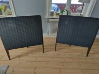
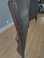
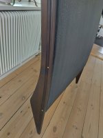
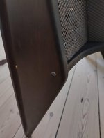
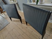
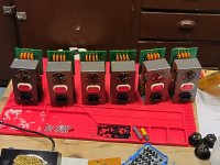
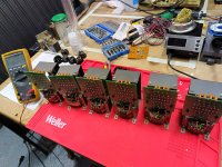
Some photos on the new refurbished with dark handcrafted spiderlegs.
Attachments
-
 IMG_20230205_142230.jpg218.6 KB · Views: 75
 -
 IMG_20230205_142237.jpg76.6 KB · Views: 67
 -
 IMG_20230205_142246.jpg262.3 KB · Views: 66
 -
 IMG_20230205_142329.jpg60.8 KB · Views: 74
 -
 IMG_20230205_142351.jpg72.6 KB · Views: 64
 -
 IMG_20230205_142409.jpg54.4 KB · Views: 75
 -
 IMG_20230205_142424.jpg288.5 KB · Views: 68
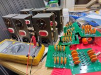

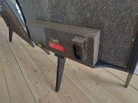
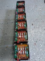
Here is a set of audio transformers restored with new resistors and upgraded to handle more than 15W power as later standard. Those Erie resistors getting high resistance values. fore example a 180K resistor is measures over 220K and I decided to replace them all. Also the weak banana jacks where replaced with some high quality German manufactured ones (no need for drilling). Protection units for the treble panels will start clipping over 2,2KVolt. Original Erine caps used when possible.
Attachments
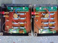
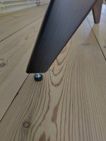
The spacing between your diodes and the mounting screws on your clamp boards is pretty small, you might have arcing from the diode legs to that grounded mounting screw. You might want to conformally coat the board or switch to plastic fasteners (not sure plastic sheet metal screws exist though).
IPC-2221 covers spacing for high voltage circuits if you are interested: https://resources.altium.com/p/using-an-ipc-2221-calculator-for-high-voltage-design
Sheldon
IPC-2221 covers spacing for high voltage circuits if you are interested: https://resources.altium.com/p/using-an-ipc-2221-calculator-for-high-voltage-design
Sheldon
- Home
- Loudspeakers
- Planars & Exotics
- Yet another ESL57 rebuild