... What you measure and to what reference point?
I don't have a nice head dummy micing device handy. Therefore, I had to resort to a simplified, and certainly less precise indirect measurement method.
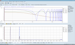
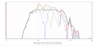
I measured the SPL of the combined mono L+R signals. R is direct sound, L is the X-Path. If there is no X-Path signal arriving at the mic, then either there is no signal on the line (as the reference, black data points on my last graph), or the X-Path signal has been completely absorbed and/or deflected. The better the XTC works, the more the red line merges into the black line. In case of a straight reference frequency response then, there would be no ripple on the summed signal: 1+0=1
Without binaural head microphone i don't see how you can measure something meaningful. This is head and pinna shadowing effect for 30 degree sound arriving direction from 3m away. It is standart speaker placement. Accurate to about 8khz. Above 8khz just not sure about accuracy. This is what head shadowing provides naturally without any XTC.
With XTC we want this line lower as possible.
You instead advocate a direct measurement method resorting to a dummy head. Then, as you say, you can easily and directly measure the xtalk-signal. The less amplitude, the better.
I chose to make the measurement without convolving a HRTF into the L (crossing) signal. Still, the results would have been similarly interpreted: The less ripple in the summed signal, the better the XTC is working. With HRTF, the ripple would have shown up differently and less intensly. The graph shows a syntesized difference between xtalk summing to direct signal with, and without HRTF

In the context of the described acoustical methods to get rid of crosstalk, it is not exactly precise to talk about XTC. Because, strictly speaking, we are not discussing a cancellation method here. It's crosstalk signal deflecting away, or crosstalk signal absorbing. In other words, rather some XTSR, like crosstalk signal removal.
Last edited:
sorry, having hard time to understandI measured the SPL of the combined mono L+R signals. R is direct sound, L is the X-Path. If there is no X-Path signal arriving at the mic, then either there is no signal on the line (as the reference, black data points on my last graph), or the X-Path signal has been completely absorbed and/or deflected. The better the XTC works, the more the red line merges into the black line. In case of a straight reference frequency response then, there would be no ripple on the summed signal: 1+0=1
you played mono signal over both speakers L and R at the same time. You first measure in the centre position(black line). And then move sideways to position of ear(red line) also playing mono over L and R ?
Yes. This is shown in the very first graph. The first center, sound path symmetric measurement correspond to black line. Then the mic was incrementally and laterally shifted to the right at positions of 5, 10, 20 and 30 samples delta between the left and the right sound paths. 30 samples pathway delta between left and right corresponds to approx. 11cm microphone distance from the center line. Which would more or less correspond to the right ear position if the nose was on the center line. The measurement at this spot is shown by the blue line (labeled '30'). The notches of this blue line more or less nicely fits the notches of the HRTF-inclusion simulation for two pulses at 30 samples offset:


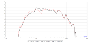
This other graph instead shows both measurements at 30 samples mic offset position to the right:

Black is free field, no obstacles in the sound paths, with the left channel muted.
Red is with a setup of a tube deflectors and a board absorber placed inline in the stereo triangle center line, e.g. symetrically affecting all sound paths, with both channels mono.
Last edited:
Now i understand. Strange for me that you get such similar curves black and red. If curves are the same so it means indirect path is completely eliminated. How is that possible? Measure with mic in ear position indirect path.only indirect speaker should play. And then measure just without deflectors. So you can see attenuation provided by deflectors. Anyway are you going to use stereo with these physical barriers?
The frequency of the lowest notch is 1600Hz, therefore lambda is 21.4cm. The obturating/deflecting monster tube had a diameter of 50cm, which is more than twice the wavelenght at the notch frequency. Therefore, such a tube certainly has the potential to be acoustically very effective for this frequency, causing at it's curved surface a strong dispersion away from the x-pathway.... similar curves black and red. If curves are the same so it means indirect path is completely eliminated. How is that possible?
As said, the (acoustically hard, therefore deflecting) tube was placed in variants of some 30cm ... 35cm in front of the measurement baseline, which nearly completely eliminated this 1600Hz notch. But it strangely enough, the 8kHz notch was unaffected and remained nearly as deep as without the tube. This upper notch then could be eliminated by an additional vertical, absorbtive board placed on the stereo triangle symmetry line between the tub and the measurement baseline.
This effective setup is nothing but a promising finding. But it's certainly not suited for everyday use.... are you going to use stereo with these physical barriers?
Last not least, I should check with real fullrange speakers having a wider dimension (think of the baffle edge diffraction effects), while placing the microphone at a regular hearing height of approx. 1.15m or so. This will include the influence of the floor reflection to be further checked for. And as for the OAF (Optical Acceptance Factor), I also should eventually check with two symetrically placed, smaller tubes instead of this huge monster right in front of your eyes. For such a twin-tube setup, eventually tubes of 25cm diameter could do the job. 25cm, because this diameter is still above lambda at the first notch, and therefore acoustically effective enough to provide an effective enough diffraction.
We happily go round in circles ...
Why not an electronic solution such as a stereo image processor? Hughes AK-100, SRS PRO220, Behringer Edison EX-1 will all reduce inter-aural crosstalk with the AK-100 being based on HRTF and utilizing directivity servos. The old Sound Concepts IR2100 will produce stunning wide stereo with good source recordings but lacks a center level adjustment. I have all of them but only the upgraded EX-1 is in my system full-time.
@bigskyaudio, I'm curious about how you feel your old Sound Concepts IR2100 processor subjectively compares to your much newer and more sophisticated XTC processors?
Why not an electronic solution such as a stereo image processor ...
It works. And nearly everybody certainly can easily set up his own, very effective DSP solution, thus ever and ever opening another, personal fun playground, e.g. along with a RPi USB gadget and CamillaDSP. In terms of creative DIYAUDIO. Been there, done that. And learning from this very competent thread Pano already mentionned here, a thread which has evolved over the years:
You might also be interested in this thread:
https://www.diyaudio.com/community/threads/fixing-the-stereo-phantom-center.277519/
Be sure to read the attached paper.
What I specifically wanted to try out here instead was to see wheter also a purely acoustic approach might work. An approach resorting by interfering physical objects within the acoustic pathways between the speakers and the listener's ears. Just for fun, to look at what extent, and at which price/compromises such a system might fit into your audio parlor.
I should have mentionned this specific goal in the title.
Interesting.I have all of them but only the upgraded EX-1 is in my system full-time.
Until a minute ago I was totally opposed conceptually to such a thing, but your post has intrigued me a lot and I've already seen that there are many second hand out there.
What is meant by upgraded?
THX
In order to not derail the kind author's thread, we can discuss analog electronic solutions for interaural crosstalk cancellation at:
https://www.diyaudio.com/community/...reo-interaural-crosstalk-cancellation.399376/
Ken & ulogon, please copy your questions over at the new thread.
https://www.diyaudio.com/community/...reo-interaural-crosstalk-cancellation.399376/
Ken & ulogon, please copy your questions over at the new thread.
- Home
- General Interest
- Room Acoustics & Mods
- Stereo inter-ear crosstalk minimizing for typical stereo loudpeaker setups - can it work?