Hi, does any one know of any really neat examples of good hard wired power supply construction that I can look at?
I am putting one together at the moment but would like to see some photo`s. I am using 2 rectifiers (one for each secondary) and would like to see some "best practise" examples for mounting bleeder resistors and bypass caps etc.
Many thanks, Jerryo
I am putting one together at the moment but would like to see some photo`s. I am using 2 rectifiers (one for each secondary) and would like to see some "best practise" examples for mounting bleeder resistors and bypass caps etc.
Many thanks, Jerryo

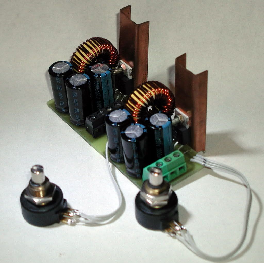
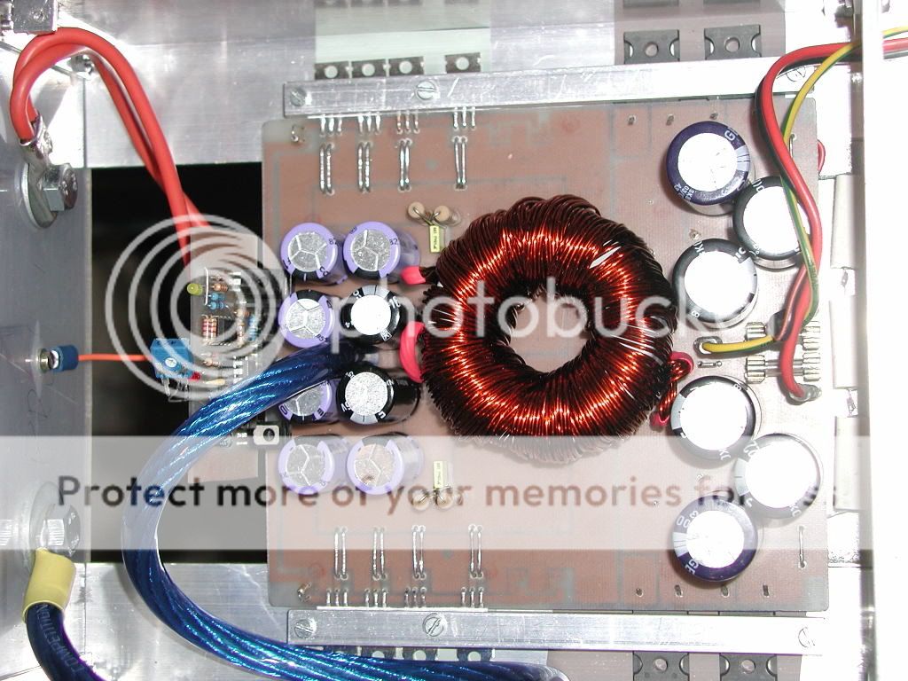
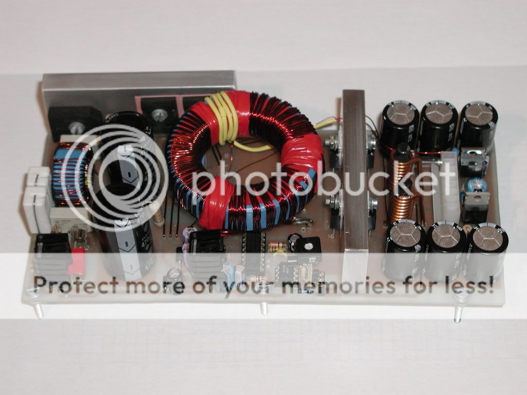
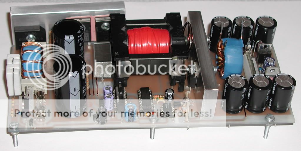
LUKA PSU will work, I have done a power supply with +-80VDC at 7AMP total power was 1120W RMS test was done on 220V 1000W halogen lamp, power supply survived successfully for 1 hour, that was a HARD test, I stoped working on that project since last year. Its intersting project, WITH FULL protection, current LIMIT, SHORT Circuit
sweet, have anything to show?LUKA PSU will work, I have done a power supply with +-80VDC at 7AMP total power was 1120W RMS test was done on 220V 1000W halogen lamp, power supply survived successfully for 1 hour, that was a HARD test, I stoped working on that project since last year. Its intersting project, WITH FULL protection, current LIMIT, SHORT Circuit
sweet, have anything to show?
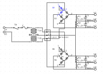
You need pictures or schematic, the shematic was takin from this site, but the protection and current limit is secret!
The project is stored in the store, I blown about 50 Mosfets in that test, and 14 IGBT, in order to reach that result.
But if you offer help. i will send you those
Picture, current limit will have to try for myself anyway and can't help you with it, anything else is a diffrent story
Ok, The circuit is not that easy, either small components, it needs a chip and 10 transistors, to do:
1- Thermal sense (power supply tem, Transformer temp)
2- Current limit
3- Short Circuit protection
4- Turn On delay
I dont think i will post that for noting! I am sorry.
I am working on that SMPS, its 3000W +_ 115VDC runing at 125KHz, Dual Output transformers, In paralell. with ONLY two IGBTs !!! also without feed back loop from the output.
Its not an easy circuit
D!
...
I dont think i will post that for noting! I am sorry.
...
Understood - how about a picture (not the schematics) for us (mere mortals) to appreciate what you are up to?

Hi Jerryo,
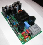
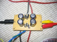
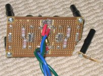
I'm not even going to try and pretend that this is "best practice" but it works well for my Gainclone powersupply constructed on Verroboard using BYV32E-200 diodes. These have two diodes per package but only one of them can use both diodes when making a bridge. I wired the spare diode in each package that can't be used so that it was shorted.
It would be nice if they made a complementary package (ie the other half of a bridge) but I couldn't find one.
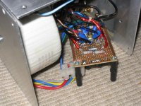
One of the pictures shows after a slight accident but a Bit of super glue fixed it. Luckily no traces of importance were damaged.
This does use dual rectifiers, but not one for each rail. I went for one rectifier per channel with a common zero volts for each. The gain clone it is connected to is an LM3886 p2p construction, with separate earth returns for critical sections of the circuit (hence the large number of leads coming to the star ground point). It works very well, and the amp is dead quiet. The only other aspect not shown is that there is a PC powersupply IEC connector with filter network taken from a dead pc powersupply before the transformer switch and fuse.
Tony.
I'm not even going to try and pretend that this is "best practice" but it works well for my Gainclone powersupply
constructed on Verroboard using BYV32E-200 diodes. These have two diodes per package but only one of them can use both diodes when making a bridge. I wired the spare diode in each package that can't be used so that it was shorted. It would be nice if they made a complementary package (ie the other half of a bridge) but I couldn't find one.
One of the pictures shows after a slight accident but a Bit of super glue fixed it. Luckily no traces of importance were damaged.
This does use dual rectifiers, but not one for each rail. I went for one rectifier per channel with a common zero volts for each. The gain clone it is connected to is an LM3886 p2p construction, with separate earth returns for critical sections of the circuit (hence the large number of leads coming to the star ground point). It works very well, and the amp is dead quiet. The only other aspect not shown is that there is a PC powersupply IEC connector with filter network taken from a dead pc powersupply before the transformer switch and fuse.
Tony.
Attachments
Pro amps
Ok if that's TRUE, then why ALL professional Amplifiers manufacturers uses the Unregulated, WITHOUT feedback from the output stage?
and 125KHZ frequency?
I will try to make some money from this project
Bye
unregulated supplys are easy, well regulated are more harder to do
like I said, post pictures, since this is photo thread
LP
Ok if that's TRUE, then why ALL professional Amplifiers manufacturers uses the Unregulated, WITHOUT feedback from the output stage?
and 125KHZ frequency?
I will try to make some money from this project
Bye
Last edited:
Help
I would like to ask the SMPS schematic diagram.
Thank you.
.... I need only one transformer and my power supply board will be ready to deliver -/+50v at 7A ....
Regards Alex
I would like to ask the SMPS schematic diagram.
Thank you.
I would like to ask the SMPS schematic diagram.
Thank you.
I would love that too... Please...
- Status
- This old topic is closed. If you want to reopen this topic, contact a moderator using the "Report Post" button.
- Home
- Amplifiers
- Power Supplies
- Power supply photo`s