After getting over my expensive mistake, things are progressing well.
I changed the 10uf capacitor at the signal input to the speaker protection to 47uF and I now have about 3.5s delay at turn on.
I tested the Vu meters. They light up nicely with the 10vac secondary from the power transformer. Perhaps more orange the yellow with the lamp on?
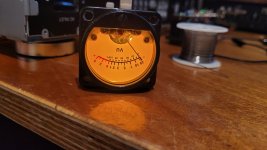
I ran a sine wave from my sig gen through it to see how the calibration was:
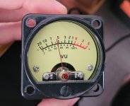
A 9v sine wave gives 55% power.
If I am doing my maths right, that means 100% is 16v which seems a bit low given 50w into 8R is 28.3v . I will test this more once I have the amps up and running and can run a larger signal through the meter.
Not the end of the world if it is as this would mean the meter would move more at lower volumes where the amp is likely to spend most of its life.
However I need to assess the possibly the meter would get damaged the amp was ever driven to full power.
I also got my new proper psus almost all soldered up pending parts from mouser. I discovered that I was 1 capacitor short on my prefered class x2 0.1uf caps for the rectifier C,RC snubbers. Also after testing the speaker protection with a no name 47uF bipolar from our local brick and mortar. Now that it is tested I have some nichicons on order.
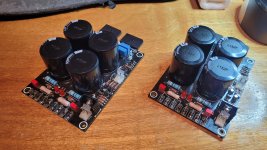
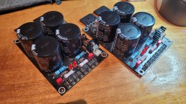
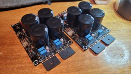
Now that these are (almost) done I can start mounting things properly in the chassis and working out a mounting solution for the transformers.
Once mounted I can work out the proper lead lengths for the transformers and then start termination and dressing them.
I changed the 10uf capacitor at the signal input to the speaker protection to 47uF and I now have about 3.5s delay at turn on.
I tested the Vu meters. They light up nicely with the 10vac secondary from the power transformer. Perhaps more orange the yellow with the lamp on?

I ran a sine wave from my sig gen through it to see how the calibration was:

A 9v sine wave gives 55% power.
If I am doing my maths right, that means 100% is 16v which seems a bit low given 50w into 8R is 28.3v . I will test this more once I have the amps up and running and can run a larger signal through the meter.
Not the end of the world if it is as this would mean the meter would move more at lower volumes where the amp is likely to spend most of its life.
However I need to assess the possibly the meter would get damaged the amp was ever driven to full power.
I also got my new proper psus almost all soldered up pending parts from mouser. I discovered that I was 1 capacitor short on my prefered class x2 0.1uf caps for the rectifier C,RC snubbers. Also after testing the speaker protection with a no name 47uF bipolar from our local brick and mortar. Now that it is tested I have some nichicons on order.


Now that these are (almost) done I can start mounting things properly in the chassis and working out a mounting solution for the transformers.
Once mounted I can work out the proper lead lengths for the transformers and then start termination and dressing them.
It verks! Noise!
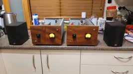
It's been a busy couple of weeks to get some noise out of some test speakers.
I had a bit of extra time time this last week as I did something to my right Achilles tendon so I couldn't train all week.
Output boards all soldered up:
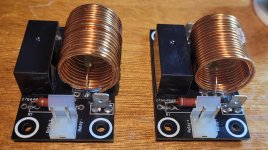
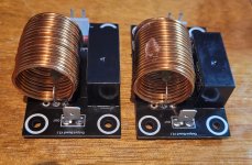
These boards integrate the output Thiel network and protection relay.
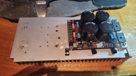
Amp board and PSU mounted up to the heatsink and partially wired up.
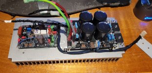
It always amazes me how long it takes to get the wiring all neatly cut, twisted, terminated, braided etc.
Here's the pair almost ready to go:
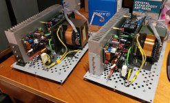
Right channel wired up ready for power:
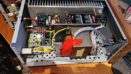
Startup went without a hitch. No magic smoke or blown fuses.
Voltages at key nodes in the circuit were as they should be.
DC offset was 0.2mV on the left channel and 0.6mV on the right channel.
Biasing was nice and smooth. The bias was set to 100mA via 44mV measured from drain to drain. Across all 4 combinations of pairs and the voltages varied up to 2mV so the lowest pair was set at 44mV.
After biasing it was time for test speakers and noise.
Now that I know they work basically as expected, tomorrow night I will get out my scope and sig gen and start torturing them to see if they scream.

It's been a busy couple of weeks to get some noise out of some test speakers.
I had a bit of extra time time this last week as I did something to my right Achilles tendon so I couldn't train all week.
Output boards all soldered up:


These boards integrate the output Thiel network and protection relay.
Amp board and PSU mounted up to the heatsink and partially wired up.

It always amazes me how long it takes to get the wiring all neatly cut, twisted, terminated, braided etc.
Here's the pair almost ready to go:

Right channel wired up ready for power:

Startup went without a hitch. No magic smoke or blown fuses.
Voltages at key nodes in the circuit were as they should be.
DC offset was 0.2mV on the left channel and 0.6mV on the right channel.
Biasing was nice and smooth. The bias was set to 100mA via 44mV measured from drain to drain. Across all 4 combinations of pairs and the voltages varied up to 2mV so the lowest pair was set at 44mV.
After biasing it was time for test speakers and noise.
Now that I know they work basically as expected, tomorrow night I will get out my scope and sig gen and start torturing them to see if they scream.
- Home
- Amplifiers
- Solid State
- Mooly's MMAMFM Monoblocks - A build log