Make sure you are tying together the PD+, ND- and NFB together before testing. See section 22, specifically 22.1 in the build guide for more information.Hello all,
Sorry for these questions, but got a little bit of an issue with building the boards.
I had some issues with power (using bench power supply ) on the IPS board (ver 3.8) , I think after setting the bias the - and + got messed up on the breadboard and since then whenever I have negative voltage the LED's D10 and D11 light up, but as soon as I give the board + power D12 and D3 come on but immediately D10 and D11 shut off. I had to replace Q12 and Q14 since they were shorted emitter to collector , as well as changing C3 since the cap was only reading 6uF instead of 10uF. The board still measures 5V across TP1 to TP2 even when the transistors were bad.
Everything else looks ok as far as I can tell, and the led's looked ok before when I put it onto the bread board previously. Just had a couple cooks in the kitchen and got things messed up a bit. The picture is with both the + and - voltage at 25 V and .005 amps.
Also, on my second set of boards (IPS 3.8 and EF-3-4 V4.0) I have tried to check the output (using signal generator at 1kHz and 100mVpp and when ever I put the ground on the speaker output the sine wave goes flat. I did not see anything wrong, and I did not want to try it with the output mosfets since the sine waves are so weird. Not smooth but kind , almost sawtooth. I did set the resistance on the POT on R109 to 485 ohms since it would not go up to 500ohms
but yet still getting full voltage (voltage that is from the power supply) between R111A and R111B
The oscilloscope image is of the board without the ground of the oscilloscope attached to anything as it just goes flat.
Sorry, for being long winded and not sure if I have explained enough.
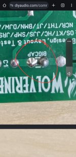
But appreciate any insight. Thanks!!!! View attachment 1307325
A couple of things I noticed from having a very quick look at your photos.when ever I put the ground on the speaker output the sine wave goes flat
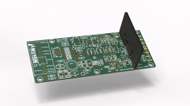
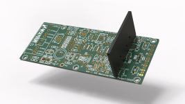
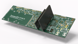
I don't see the IPS board plugged into the output stage board.
You can't drive a speaker load without output transistors installed.
The solder bridge on C1 is missing.
I don't see the 9.1k parallel resistor with R17 for low voltage power start up.
Check your oscilloscope probe is well connected.
Some more board photos would be good. It looks like the boards could do with a bit more cleaning.
Attachments
Last edited:
were you following the build guide?Hello all,
Sorry for these questions, but got a little bit of an issue with building the boards.
I had some issues with power (using bench power supply ) on the IPS board (ver 3.8) , I think after setting the bias the - and + got messed up on the breadboard and since then whenever I have negative voltage the LED's D10 and D11 light up, but as soon as I give the board + power D12 and D3 come on but immediately D10 and D11 shut off. I had to replace Q12 and Q14 since they were shorted emitter to collector , as well as changing C3 since the cap was only reading 6uF instead of 10uF. The board still measures 5V across TP1 to TP2 even when the transistors were bad.
Everything else looks ok as far as I can tell, and the led's looked ok before when I put it onto the bread board previously. Just had a couple cooks in the kitchen and got things messed up a bit. The picture is with both the + and - voltage at 25 V and .005 amps.
Also, on my second set of boards (IPS 3.8 and EF-3-4 V4.0) I have tried to check the output (using signal generator at 1kHz and 100mVpp and when ever I put the ground on the speaker output the sine wave goes flat. I did not see anything wrong, and I did not want to try it with the output mosfets since the sine waves are so weird. Not smooth but kind , almost sawtooth. I did set the resistance on the POT on R109 to 485 ohms since it would not go up to 500ohms
but yet still getting full voltage (voltage that is from the power supply) between R111A and R111B
The oscilloscope image is of the board without the ground of the oscilloscope attached to anything as it just goes flat.
Sorry, for being long winded and not sure if I have explained enough.
But appreciate any insight. Thanks!!!! View attachment 1307325 View attachment 1307326 View attachment 1307327 View attachment 1307328 View attachment 1307329 View attachment 1307330
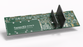
Not related, but the use of thermal compound looks excessive.
Last edited:
Hi TJ,Hello all,
Sorry for these questions, but got a little bit of an issue with building the boards.
I had some issues with power (using bench power supply ) on the IPS board (ver 3.8) , I think after setting the bias the - and + got messed up on the breadboard and since then whenever I have negative voltage the LED's D10 and D11 light up, but as soon as I give the board + power D12 and D3 come on but immediately D10 and D11 shut off. I had to replace Q12 and Q14 since they were shorted emitter to collector , as well as changing C3 since the cap was only reading 6uF instead of 10uF. The board still measures 5V across TP1 to TP2 even when the transistors were bad.
Everything else looks ok as far as I can tell, and the led's looked ok before when I put it onto the bread board previously. Just had a couple cooks in the kitchen and got things messed up a bit. The picture is with both the + and - voltage at 25 V and .005 amps.
Also, on my second set of boards (IPS 3.8 and EF-3-4 V4.0) I have tried to check the output (using signal generator at 1kHz and 100mVpp and when ever I put the ground on the speaker output the sine wave goes flat. I did not see anything wrong, and I did not want to try it with the output mosfets since the sine waves are so weird. Not smooth but kind , almost sawtooth. I did set the resistance on the POT on R109 to 485 ohms since it would not go up to 500ohms
but yet still getting full voltage (voltage that is from the power supply) between R111A and R111B
The oscilloscope image is of the board without the ground of the oscilloscope attached to anything as it just goes flat.
Sorry, for being long winded and not sure if I have explained enough.
But appreciate any insight. Thanks!!!! View attachment 1307325 View attachment 1307326 View attachment 1307327 View attachment 1307328 View attachment 1307329 View attachment 1307330
First off I would carefully go over all of the steps in the build guide, especially the checks before power up.
Let us know if find something obviously a problem with these steps first please.
Stuarts comments about the solder for the ground connections and the oscilloscope probe is very important to check also.
- Dan
The 4th group buy has been up for one month now. So I'll be finalising things this week. The order with the board house will be placed this weekend.Hi, may I ask about the status of the 4th group buy. Is there already a estimated dekivery schedule available
A big thank you to all the forum members who have registered. The response has been very well received.
If anyone is still sitting on the fence now is the time to get your order in before the 4th group buy opportunity closes.
I'll keep everyone informed once the order has been placed.
Thanks @danieljw @stuartmp and @mainframe99
I took off the IPS board just for a better view of the board.
Totally missed the C1 bridge, nice catch!!!!
Old heat compound + big squeeze = big mess. :~)
I do have to clean that up.
Will go over and retest everything when I get back from my jury duty. Inhaling solder fumes is much more interesting than looking a walls of a court house.
I went through the build forum here and did find the R17 9.1K parallel resistor (and pictures for my brain dead self) , but it is definitely not in the revision of the build guide that I have. It should be on page 37 of the build guide that I have (Rev 37 01-09-23), but it is not referenced. (irony must be my middle name). Did another read through and did a "Find" on the pdf and only two references to R17 but only toward the BOM installs.
Is there another newer build guide that is available ? Thanks.!!!!
Is there another newer build guide that is available ? Thanks.!!!!
The latest version is 41 07-10-2023 (dd-mm-yyyy)Rev 37 01-09-23
See page 37, 38 & 51
Use your Dropbox Link to download the latest file.
I have had a bunch of inquiries on heatsinks, the new heatsinks are now available for those who were looking. These are flat black anodized, driver heatsink tapped, and pins installed. I currently have the CCS/VAS and predriver heatsinks on hand for EF3-4 boards, and the driver heatsinks arriving shortly for the EF3-3 boards. These heatsinks will only fit GB1-GB3 boards.
The new group buy boards will be using updated pin heatsinks, and whoever is interested in those can you let me know, so I have a rough idea on order qty.
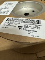
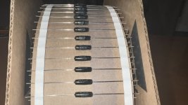
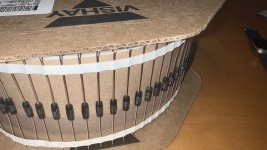
I also received a bulk order of CPF emitter resistors. They are 500mOhm 1% 150ppm, they will be lead formed and ready to install.
Heatsinks
EF3-3 $65 - 2 CCS/VAS | 2 Predriver | 2 Driver
EF3-4 $40 - 2 CCS/VAS | 2 Predriver | No Driver Heatsink
Vishay Emitter Resistors
EF3-3 $70 Set of 24
EF3-4 $90 Set of 32
The new group buy boards will be using updated pin heatsinks, and whoever is interested in those can you let me know, so I have a rough idea on order qty.
I also received a bulk order of CPF emitter resistors. They are 500mOhm 1% 150ppm, they will be lead formed and ready to install.
Heatsinks
EF3-3 $65 - 2 CCS/VAS | 2 Predriver | 2 Driver
EF3-4 $40 - 2 CCS/VAS | 2 Predriver | No Driver Heatsink
Vishay Emitter Resistors
EF3-3 $70 Set of 24
EF3-4 $90 Set of 32
Attachments
I have some
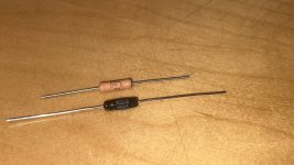
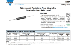
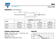
Vishay Emitter Resistors Mills MRA-05 0.56ohm 5W
Mills MRA-05 0.56ohm $10 Set of 24
Mills MRA-05 0.56ohm $12 Set of 36
These MRA-05 are same size as the cpf3 resistors.
Vishay Emitter Resistors Mills MRA-05 0.56ohm 5W
Mills MRA-05 0.56ohm $10 Set of 24
Mills MRA-05 0.56ohm $12 Set of 36
These MRA-05 are same size as the cpf3 resistors.
Attachments
- Home
- Amplifiers
- Solid State
- DIY Class A/B Amp The "Wolverine" build thread