Hello CWelsh52 and everyone, I'm glad that active crossover works well for you, but it doesn't make things any easier for me. I still don't know which type of amplifier is best for direct connections to a horn speaker with a recommended 800 Hz crossover frequency and a 15 inch woofer? Thanks
Hello CWelsh52 and everyone, I'm glad that active crossover works well for you, but it doesn't make things any easier for me. I still don't know which type of amplifier is best for direct connections to a horn speaker with a recommended 800 Hz crossover frequency and a 15 inch woofer? Thanks
Well it kind a depends on what sound you like. At the moment, i am driving a 15" bass woofer with an F6 and a Fulltone driver with the ACA Mini, with a crossover point (-6 dB) at 160-170 Hz. All driven by a ZM iron Pre and a NP FR EQ before the BiAm6-24. The ACA Mini is to be exchanged by a ZM LuDEF amp very soon.
Some of the questions you can consider, for choosing an amp:
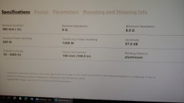
What is the sensitivity of the driver?
What is the resistance (8/4/??)?
What kind of sound do you like? Consider harmonics, both the content (neg 2nd dominating, 3rd dominating etc.) and the amount - to my ears, too much harmonics content, can make some simpler music sound out of this world, while take the life out of more complex music
Some might use a class D for bass and choose a glorious sounding, low efficiency class A amplifier for mid and tweeter.
There is no correct answer, the fun is in the journey

By the way for the right music i highly recommend the ACA Mini, it really sounds good - instruments and voices are magical with it.
On one of yours the lead spacing looks to be 15mm. I think you want 5mm for that figure. I can't see that data on your second cap variant. For what it's worth I used these:I'm trying to put together a DigiKey order and am a bit stumped on the C & C/2 caps. My target crossover point is 650 hz and I have calculated C = 9.231 (10) nF = .010 mF = 10,000 pF and C/2 = 4.615 nF = .0047 mF = 4,700 pF.
I've never ordered from DigiKey before and I'm having a hard time figuring out which capacitors I'm actually supposed to order. I have identified FKP1G021004B00KSSD and FKP1G014704B00KSSD, but don't know for sure that I am correct. And, of course, please let me know if I've made a mistake in my calculations.
Thank you!
https://www.digikey.com/en/products/detail/wima/MKS2D021001A00MSSD/9370565
https://www.digikey.com/en/products/detail/wima/FKP2D014701G00HSSD/9370190
These for my first variant and recall the crossover point is as you calculated. I've since changed those caps to cross ~ 100hZ.
Paid the princely sum of $3 for a wood +mdf chassis. These crossovers are so quiet at least in my experience require no shielding, I had it sitting naked on top of my Iron Pre no problems.
Thanks, @JKiriakis. With help from others, I did get it all figured out.
Pretty cool chassis you've got there!
Pretty cool chassis you've got there!
I was involved in evaluating these crossovers early on in the piece.
Just be aware the slope refers to the acoustic slope. Given no driver is ever ideal you will need to tweak the crossover voltage drive.
I recommendation is to make a voltage drive measurement in REW and Save these curves.
Then use these curves as objecti
Just be aware the slope refers to the acoustic slope. Given no driver is ever ideal you will need to tweak the crossover voltage drive.
I recommendation is to make a voltage drive measurement in REW and Save these curves.
Then use these curves as objecti
The other thing to bear in mind is the LR24 low and high pass filters have non symmetrical group delay. What this means is that you will need to take this into consideration when looking at the driver offset. The effect is that the on axis lobe will be tilted.
You can incorporate analogue 3rd order Bessel all pass filter to compensate for the difference in the group delay.
The alternative is to introduce phase compensation by shifting one of the crossover points slightly. This will move the on axis axial response to produce a flat response in the crossover region. Vance Dickason covers this in the Loudspeaker Cookbook.
It’s more of an issue for tweeter crossover points than say a horn @ 800 hertz.
Above all measure your native driver frequency response on the loudspeaker baffle before commencing the active filter design process.
Also use DATS3 to check the impedance for driver resonances.
Try and also measure the 30 degree off axis response as well. This will help you realise the optimum crossover point in a two way design.
Tip. Do not attempt a nearfield indoor measurement with the mic right on the dust cap. This will cause errors in both the low and high frequency response. Your measurements should be at 3 x the diameter of the driver. Use 1/12 octave smoothing. Better still do it outside a a chair if it’s not raining to avoid loosing resolution lost with Gating.
I've taken the plunge and ordered two boards for a 3-way speaker project. I've read the entire thread, and strayed into a couple of side quests like balanced operation and JFET buffers.
I've also ordered a bunch of LSK170's because clearly I like the deep end. Mostly the conversation around FETs in here is about biasing, so have that well understood. Where I'm still missing context is around matching. It's been mentioned in passing a few times, but there seems to be contradictions. I've also learned that when smart people seem to spout contradictions, there's something interesting to learn. It was never contradictory, but lacking context.
There looks to be some fuss around matching among builders here, then N.P. drops this nugget in post #932:
Everyone is scrambling to "match" their JFETs, when Mr. Pass is casually hand-waiving it away and blasting Idss values into the stratosphere, well beyond the J Fringe. And to my layman, tiny brain it seems logical that pairing a J113 (Q2, CCS) with an LSK170 (Q1, Follower) would be quite impossible to match, they are quite different parts. For instance, J113 has an Idss of 2-? (I've seen 40mA+ in other's measurements?), whereas the LSK170 is 6-12mA.
Quote below is not about matching per se, but builders seem to want to match for the purposes of staying within Idss "limits". From this article elsewhere on the Internet:
Huh? No wonder there's confusion around this topic. There's a devil lurking in the details, I suspect. On to the questions:
1. In what context is matching FETs important for this particular circuit? Vp? Minimum Idss? Between Q1 and Q2? Horizontally across channels? Vertically along one signal/filter path?
2. I see Beyond the J Fringe has LS parts in a push-pull circuit, and Toshiba parts in another. Can drain current overdrive work safely in the context of this crossover?
3. If the answer to the above question is no, what are the considerations/pros/cons for dropping drain currents from the stock 8-10ma to my lowest common denominator ~6.5mA?
Wow long post. Thank you Nelson Pass for this fantastic design, and thanks to all the folks in here for sharing your knowledge and builds!
I've also ordered a bunch of LSK170's because clearly I like the deep end. Mostly the conversation around FETs in here is about biasing, so have that well understood. Where I'm still missing context is around matching. It's been mentioned in passing a few times, but there seems to be contradictions. I've also learned that when smart people seem to spout contradictions, there's something interesting to learn. It was never contradictory, but lacking context.
There looks to be some fuss around matching among builders here, then N.P. drops this nugget in post #932:
Matching is nice, but not crucial. It is convenient to consider 2SK170 / LSK170 in the
follower positions and continue to use J113 as constant current sources.
Everyone is scrambling to "match" their JFETs, when Mr. Pass is casually hand-waiving it away and blasting Idss values into the stratosphere, well beyond the J Fringe. And to my layman, tiny brain it seems logical that pairing a J113 (Q2, CCS) with an LSK170 (Q1, Follower) would be quite impossible to match, they are quite different parts. For instance, J113 has an Idss of 2-? (I've seen 40mA+ in other's measurements?), whereas the LSK170 is 6-12mA.
Quote below is not about matching per se, but builders seem to want to match for the purposes of staying within Idss "limits". From this article elsewhere on the Internet:
It should be apparent that expecting to operate a JFET with an IDSS of 1mA with a drain current of more than 1mA won't work - ideally the quiescent drain current will be somewhere between 50% and 85% of the rated (or measured) IDSS for minimum distortion.
Huh? No wonder there's confusion around this topic. There's a devil lurking in the details, I suspect. On to the questions:
1. In what context is matching FETs important for this particular circuit? Vp? Minimum Idss? Between Q1 and Q2? Horizontally across channels? Vertically along one signal/filter path?
2. I see Beyond the J Fringe has LS parts in a push-pull circuit, and Toshiba parts in another. Can drain current overdrive work safely in the context of this crossover?
3. If the answer to the above question is no, what are the considerations/pros/cons for dropping drain currents from the stock 8-10ma to my lowest common denominator ~6.5mA?
Wow long post. Thank you Nelson Pass for this fantastic design, and thanks to all the folks in here for sharing your knowledge and builds!
Attachments
determine which part of buffer cell is signal, which is CCS
logically - precioussssss JFet is signal one, cheap drek JFet is CCS
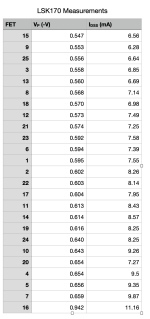
measure all your precious JFets for Idss, make pairs and use pairs in same position of both channels; say HP both channels one pair, LP both channels second pair
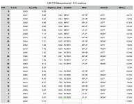
measure all your drek JFets for idss,, derive source resistance for target Iq to pair them with preciousssss JFets
say that you have 10mA precioussss Idss Jfet in HP cell; say that you want to push it to 90% of Idss, that's 9ma; find source resistor value to bias drek JFet to 9mA; when you pair these two - preciousssssssss JFet biased with drek JFet 9mA CCS ......... that's it
work cell by cell , and you'll have it
edit: in case that you post exact schmtc, I can be very specific, regarding nomenclature
that's only way to avoid broken telephones effect
logically - precioussssss JFet is signal one, cheap drek JFet is CCS
measure all your precious JFets for Idss, make pairs and use pairs in same position of both channels; say HP both channels one pair, LP both channels second pair
measure all your drek JFets for idss,, derive source resistance for target Iq to pair them with preciousssss JFets
say that you have 10mA precioussss Idss Jfet in HP cell; say that you want to push it to 90% of Idss, that's 9ma; find source resistor value to bias drek JFet to 9mA; when you pair these two - preciousssssssss JFet biased with drek JFet 9mA CCS ......... that's it
work cell by cell , and you'll have it
edit: in case that you post exact schmtc, I can be very specific, regarding nomenclature
that's only way to avoid broken telephones effect
https://audioxpress.com/article/JFETs-The-New-Frontier-Part-1
https://audioxpress.com/article/JFETs-The-New-Frontier-Part-2.html
Some useful reading on the subject of jfet testing.
As l recall when l ordered 1000 prices in the BL grade we matched then in groups as discussed above.
https://audioxpress.com/article/JFETs-The-New-Frontier-Part-2.html
Some useful reading on the subject of jfet testing.
As l recall when l ordered 1000 prices in the BL grade we matched then in groups as discussed above.
I've read those articles a few times now, I pick up something new every time.
Thanks Zen Mod for the tips. I'll work from lowest to highest Idss, matching as close as possible from left to right. What do you see as the considerations for driving the follower at 60% vs at 90% of Idss?
I'm still in the dark about question 2, but I'll leave it as few are talking about overdriving FETs. I'll stick to the conventions.
As for question 3, I've had lengthy Q&A sessions with a chat bot. Here's what it's telling me. I'd like to run it by this thread in case it's hallucinating 'facts'.
As long as the FET is operating in it's saturation region, the actual source-to-drain mA doesn't matter, however too high can cause clipping. Too low and it may no longer be operating in a linear fashion and be more susceptible to noise. It also reckons I should be putting lower Idss FETs on the input buffers for higher input impedance and lower noise. Higher Idss parts should go be on the output buffers to drive higher loads.
It also mentioned higher Idss parts having more headroom for input swings. Would it be optimal to bias a higher Idss FET at a lower percentage of it's Idss for maximum headroom?
Is this bot making sense?
Here's what I've come up with so far, most biased to 90% of follower Idss, and the BP and LP outputs at 80-85%.
Attachments
I would like to go the active route, having read this thread I feel that I have not gained the necessary information to give me confidence to proceed.
I believe there was an earlier mention of a build guide, unfortunately I cannot find.
Q1, is there a method of adjustment parameters using a DVM only.
Q2, is there a base setting ( giving a starting point).
Many Thanks in anticipation.
I believe there was an earlier mention of a build guide, unfortunately I cannot find.
Q1, is there a method of adjustment parameters using a DVM only.
Q2, is there a base setting ( giving a starting point).
Many Thanks in anticipation.
Q2, is there a base setting ( giving a starting point).
From Nelson:
The frequency pots go higher in frequency with clockwise rotation. The center point of the
resistance range is close to > mark on the board and using a small flat blade screwdriver you
would point the arrow on the rotating top of each pot to this spot
I built my 6-24 xover a while back, using 2SK170's, carefully matched, etc.In what context is matching FETs important for this particular circuit?
After thinking about matching, since the buffers are all unity gain, why do the 2SK170 JFET's need to be matched?
They don't really, but I like to know the Idss of the 2SK170's walking in, so that I
can run them at little less current, this sourced by the el cheapo J113's with
appropriate Source resistors to set the current. This is one of the conveniences
of the kit, and why those Source resistors are provided.

can run them at little less current, this sourced by the el cheapo J113's with
appropriate Source resistors to set the current. This is one of the conveniences
of the kit, and why those Source resistors are provided.
- Home
- Amplifiers
- Pass Labs
- DIY biamp 6-24 crossover