Hello everyone,
I'm working on a project that's based around the idea of "digitally controlled analog". This project should include some basic EQ functionality to show the usefulness of other parts of the device.
Theoretically, a Baxandall style circuit should be perfect, so I went with the "Active / Single Bass Capacitor" variant from https://www.guitarscience.net/tsc/baxandall_2.htm#
My first idea of implementing digital control capabilities were digital potentiometers, which lead me to the same problem with massively distorted audio as described in this post from 2004: https://www.diyaudio.com/community/threads/digitally-controlled-baxandall.28022/
Given the age of that post, I'm curious whether nothing has changed over the last 20 years - at least I was using modern digipots that were designed for higher analog voltage levels: https://www.microchip.com/en-us/product/mcp41hv51
(The pots were powered with +/-15V and the voltage across them was never near their maximum.)
My next best idea would be motorized potentiometers, but I'm not sure whether dealing with motor control circuitry is worth it, considering their performance.
Since the values need to change in real time, preconfigured values that are switched by relays aren't really an option either - the zipper noise of digipots would already be prolematic.
The eq feature is too important for the project to be left out, but not important enough to go down another rabbit hole like vactrols...
Has anyone got another idea? Maybe in the form of a different digipot, a different eq circuit or a different way of adding digital control to existing circuitry. 🤔
Thank you all very much in advance!
I can imagine that zipper noise could be irritating/problematic, but in steady-state I don't understand why distortion should be "massive."
Would you quantify what you mean by massive? Can you post a circuit you're experimenting with, showing IC types and supply voltages, and what problems you're experiencing?
Thanks!
Would you quantify what you mean by massive? Can you post a circuit you're experimenting with, showing IC types and supply voltages, and what problems you're experiencing?
Thanks!
Well, "massive" means that you can barely recognize any music that's being fed through - so we're not talking about 1% or even 5% THD.
The circuit is literally the one from https://www.guitarscience.net/tsc/baxandall_2.htm# with digipots instead of regular ones.
For op amps I tried TL071 and NE5534. Everything is running on +/-15V from 2 (linear) lab bench power supplies with a common ground.
With regular pots everything is working fine, so it must have to do with the digipot.
I also posted the question on Microhip's forum where someone suggested buffering the wiper to avoid excessive current and thereby resistance modulation, but adding another op amp at the wiper only made things worse.
Weirdly, the problem seems to depend on the digipot's wiper position: At one end (boosting) it works reasonably well and gradually get's worse towards the other end (cutting). At the problematic end the digipot somehow lowers the eq's overall gain - the pass band is noticeably attenuated.
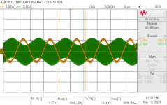
I'll attach a screenshot of an audio sweep (using Room EQ Wizard as a cheap audio analyzer).
For now I'll use a different circuit as I need to continue with the project. But it's still bugging me why a digipot that's specifically designed for higher analog voltages won't work in this circuit... 🤔
The circuit is literally the one from https://www.guitarscience.net/tsc/baxandall_2.htm# with digipots instead of regular ones.
For op amps I tried TL071 and NE5534. Everything is running on +/-15V from 2 (linear) lab bench power supplies with a common ground.
With regular pots everything is working fine, so it must have to do with the digipot.
I also posted the question on Microhip's forum where someone suggested buffering the wiper to avoid excessive current and thereby resistance modulation, but adding another op amp at the wiper only made things worse.
Weirdly, the problem seems to depend on the digipot's wiper position: At one end (boosting) it works reasonably well and gradually get's worse towards the other end (cutting). At the problematic end the digipot somehow lowers the eq's overall gain - the pass band is noticeably attenuated.
I'll attach a screenshot of an audio sweep (using Room EQ Wizard as a cheap audio analyzer).
For now I'll use a different circuit as I need to continue with the project. But it's still bugging me why a digipot that's specifically designed for higher analog voltages won't work in this circuit... 🤔
Attachments

Someone got a passive non feedback based hi filter to work
https://medium.com/@enriqueramrezma...analog-guitar-effect-with-an-app-f962dfb37dc9
https://medium.com/@enriqueramrezma...analog-guitar-effect-with-an-app-f962dfb37dc9
I tried the MCP41HV51 (100k version).Which Microchip version did you select?
All models from the HV series should perform the same (SPI vs. I²C and 128 or 256 taps).
Someone got a passive non feedback based hi filter to work
I've also used those digipots for a simple high pass filter, which works as it should.
However, my new circuit is active, with the big difference that I'm using the digipot as an adjustable resistor (rheostat) to adjust the gain of an inverting amplifier rather than having all three terminals connected.
So, I'm not sure whether it has anything to do with the usage in active filters or whether it's a problem that only occurs when all three terminals are connected. 🤔
Disclaimer: I don't play on the level of the EE types around here, and I'm getting started with digipots myself. I have an existing, fairly complex active 4 band eq (opamps using bipolar 18v supplies) that I would like to adapt to digipots. So I'm interested as well, but at the lower end of the learning curve ")
In the rheostat configuration, do you have the unused leg tied to the wiper, as it were?
In the rheostat configuration, do you have the unused leg tied to the wiper, as it were?
I scratched my head, read the full datasheet for the digipot, looked at the (classic) circuit and.... really can't get why that doesn't work. For a while I was trying the idea of the small current leak the digipot has but I can't see how that would affect the opa/circuit anything like that.
In the rheostat configuration, do you have the unused leg tied to the wiper, as it were?
With regular pots you'd want to do that because the connection to the wiper can be intermittent while turning the pot.
I'm not so sure how this translates to digipots, but the datasheet shows an unconnected pin in all application examples where only an adjustable resistance is needed (e.g. figure 8-5, page 61), so leaving the pin floating should be fine. Besides, that only comes into play while changing the setting.
I hope I'm wrong, but just tossing it out - could it be a(nother) fake chip situation?
I got the ICs fom Mouser, so I don't consider that a possibility.
I scratched my head, read the full datasheet for the digipot, looked at the (classic) circuit and.... really can't get why that doesn't work.
Me neither...
I'm second guessing my soldering - since the HV digipots are only available as SMDs I soldered one to a breakout pcb for testing on a breadboard. But measuring the resistance with a multimeter showed no signs of any defects and by connecting A and B to +/-15V I could test the digipot as a crude DAC - turning it up and down resulted in the expected triangle waveform on the oscilloscope.
I also rewired the entire breadboard to rule out any errors, which made no difference. Also, the circuit works perfectly fine with a regular pot.
Searching the web, I only found the aforementioned post from 2004, which lead me to this forum.
I was hoping to get an answer from Microchip, but their forum doesn't really seem to be interested in audio: https://forum.microchip.com/s/topic/a5CV40000000WntMAE/t394416
When I was building my TV 5.1 preamp I wanted tone controls on everything. I found the NJW1119AHello everyone,
I'm working on a project that's based around the idea of "digitally controlled analog". This project should include some basic EQ functionality to show the usefulness of other parts of the device.
Theoretically, a Baxandall style circuit should be perfect, so I went with the "Active / Single Bass Capacitor" variant from https://www.guitarscience.net/tsc/baxandall_2.htm#
My first idea of implementing digital control capabilities were digital potentiometers, which lead me to the same problem with massively distorted audio as described in this post from 2004: https://www.diyaudio.com/community/threads/digitally-controlled-baxandall.28022/
Given the age of that post, I'm curious whether nothing has changed over the last 20 years - at least I was using modern digipots that were designed for higher analog voltage levels: https://www.microchip.com/en-us/product/mcp41hv51
(The pots were powered with +/-15V and the voltage across them was never near their maximum.)
My next best idea would be motorized potentiometers, but I'm not sure whether dealing with motor control circuitry is worth it, considering their performance.
Since the values need to change in real time, preconfigured values that are switched by relays aren't really an option either - the zipper noise of digipots would already be prolematic.
The eq feature is too important for the project to be left out, but not important enough to go down another rabbit hole like vactrols...
Has anyone got another idea? Maybe in the form of a different digipot, a different eq circuit or a different way of adding digital control to existing circuitry. 🤔
Thank you all very much in advance!
digitally controlled stereo 3 band tone control chip. Being Japanese it's a little odd to program but it
works very well. I bought mine from AliExpress and they are still available. This is a link to a DIY thread.
https://www.diyaudio.com/community/...-tone-control-preamp-njw1119a-chipset.268083/
G²
Attachments
Shematic in the first post in the threadAre you able to post a schematic? That would make it easier to pose questions and offer suggestions.
Thanks!
JFETs could be configured as variable resistors. Then it's a matter supplying them with analogue voltage, e.g. from 8-12 bit DAC outputs on the uC, or PWM.
You also haven't mentioned what kind of application it's for. A guitar pedal probably wouldn't have to be ultra-linear to start with. And just playing with JFETs could create lots of 'tone' in its own right.
You also haven't mentioned what kind of application it's for. A guitar pedal probably wouldn't have to be ultra-linear to start with. And just playing with JFETs could create lots of 'tone' in its own right.
I assume the opamp supply pins are well bypassed. When testing, be sure to use x10 scope probes to minimize the chance that shunt capacitance from the probes provokes oscillation.
My suspicion is that the opamp may be oscillating, probably due to stray capacitance within the pot's mux switching network to circuit common. I suggest setting the pot to a problematic position and probing the opamp output with your scope to look for evidence of oscillation. As a possible remedy, try tacking a 100pF cap from opamp output to inverting input. If this looks promising, explore with a simulator or experimentally to find an appropriate value for best performance vs. stability over all pot positions.
My suspicion is that the opamp may be oscillating, probably due to stray capacitance within the pot's mux switching network to circuit common. I suggest setting the pot to a problematic position and probing the opamp output with your scope to look for evidence of oscillation. As a possible remedy, try tacking a 100pF cap from opamp output to inverting input. If this looks promising, explore with a simulator or experimentally to find an appropriate value for best performance vs. stability over all pot positions.
This sounds like an added feature not present in the guitar article. Would you provide a simple sketch of the inverting gain amp idea? Thanks.However, my new circuit is active, with the big difference that I'm using the digipot as an adjustable resistor (rheostat) to adjust the gain of an inverting amplifier rather than having all three terminals connected.
It's literally the standard Baxandall schematic with digipots instead of regular ones. My project's schematic is spread out across multiple sheets, so it makes no sense to post that.Are you able to post a schematic?
I included a link to it, but I'll also attach a screenshot.Shematic in the first post in the thread
The used op amps were TL071 and NE5534 (made no difference), the pot was the MCP41HV51 100k, power was +/-15V and for the SPI signals I used an Arduino Micro (powered via USB, common GND).
Thank you very much for the hint! That chip really has an impressive spec list, but I'd prefer something that is readily available from Mouser/Digikey/Farnell/...I bought mine from AliExpress and they are still available
Good point - I completely forgot to mention that!You also haven't mentioned what kind of application it's for.
In general, I'd like to get familiar with digipots as they would be useful for various projects that I have in mind (including guitar pedals).
However. the current project falls into the "studio outboard gear" category - maybe even "mastering grade" in a future revision. So, it needs to be fairly high quality, which is why I'd like to stick with +/-15V rather than squeezing the signal through any +/-5V ICs.
In the meantime I've also found a document by THAT featuring VCA based eq circuits: https://www.thatcorp.com/datashts/AES13-031_Digitally_Controllable_Audio_Filters.pdf
All those things were taken care of.I assume the opamp supply pins are well bypassed. When testing, be sure to use x10 scope probes to minimize the chance that shunt capacitance from the probes provokes oscillation.
That might actually be the case. 🤔 It can be a bit challenging at times to tell whether something is oscillating or it's just the inherent noise of breadboarded circuits. I'll definitely give that another try, once I find some time.My suspicion is that the opamp may be oscillating, probably due to stray capacitance within the pot's mux switching network to circuit common.
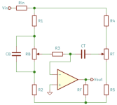
In theory, you can boost the highs by (partly) removing them from the feedback network of an amplifier. So basically another gain control just for high frequencies. I'll include a rough sketch with a non inverting op amp: R3 is the adjustable 100k digipot with 1k in series and the following high pass filter should prevent any high frequency oscillations. The only "issue" with this circuit is that it can only boost the highs (+6dB), but not cut them - which is fine for my application.This sounds like an added feature not present in the guitar article. Would you provide a simple sketch of the inverting gain amp idea? Thanks.
Attachments

That's actually it! 👍My suspicion is that the opamp may be oscillating
I set everything up on a breadboard once again and did some more testing:
The low frequency half of the circuit works just as well with the digipot as it does with a regular one. So that part is fine.
The high frequency part however, does indeed oscillate when the pot is set to cut. Boosting works as expected.
Interestingly, this even happens with a regular (trim) pot. So, the problem doesn't even seem to be connected to the digipot.
What else could be causing this effect? Baxandall tone controls are "tried and trusted". Could it be an issue with the breadboard or the used TL071? 🤔
It does reduce the oscillation's amplitude a bit, but even with 1nF the problem is far from gone.try tacking a 100pF cap from opamp output to inverting input
Could the phase shift caused by the treble capacitor be the culprit? After all it's in the feedback network and might turn the negative feedback into positive feedback that doesn't get attenuated enough depending on the pots position. Are high quality caps important for this circuit? 🤔
Attachments

I'm offering some suggestions purely on instinct.
I would try making Rf=0 and see what effect that may have. (If the system needs a 600R output impedance, it should be in series with output, not included within feedback network.)
Next experiment would install a short from opamp out to - input. This should make the opamp a unity gain stage. It should be stable, bit if it isn't, my bet is that therein lies the problem.
P.S. Make sure you're using x10 scope probes.
- Home
- Design & Build
- Electronic Design
- Digitally controlled analog shelving filter (low/high shelf eq)