With a proper quality transformer with blind winding between primary amd secondary, and with magnetic shield, it shouldn't be as critical. BUT, properly done toroids are scarce so i'd follow the advice above. We are lucky there are amazing toroids from Trafomatic here in Serbia.

If anyone interested for AD1862 chips i am selling 2 pairs
https://www.diyaudio.com/community/threads/ad1862-2-pairs-new.412359/#post-7675235
https://www.diyaudio.com/community/threads/ad1862-2-pairs-new.412359/#post-7675235
 .
.Hey colleagues, please show me some lineage!!! Of how your CD players, TVs, raspberries and Nas are plugged to this wonderful dac via USB, spdif, coax!!!
Trying to figure out how to put it ad good use apart from my old CD player!
PS. I've a qobuz sub now, I'd like to use that with this dac!
Trying to figure out how to put it ad good use apart from my old CD player!
PS. I've a qobuz sub now, I'd like to use that with this dac!
You should start at page one of this thread with a notebook and pencil ready for note taking, there are many, many builds and tons of pictures showing how diyers implement the AD1862 chip plus several others. Go to the Electrodac link Miro attached in post#1, all the info you need to start is there. Download and read the AD1862 datasheet. 😉
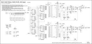
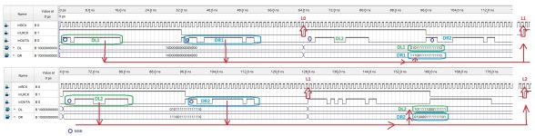
DAC702 prototype schematic 😎
Glue Logic piece ... at least in simulator it works
I2S 64-Bit Sample Glue Logic for DAC702 principle (bipolar output) in theory:
Glue Logic piece ... at least in simulator it works
I2S 64-Bit Sample Glue Logic for DAC702 principle (bipolar output) in theory:
- 15-Bit serial data delay for sample aligning with the LRCK rising edge* (IC1, IC2)
- 16-Bit serial data delay with parallel out buffer for DAC1 (IC3, IC4)
- 16-Bit serial data delay (IC5, IC6)
- 16-Bit serial data delay with parallel out buffer for DAC2 (IC7, IC8)
- Inverting each MSB of the I2S code to get COB code (offset binary) for bipolar output (IC9, IC10)
- *LRCK rising edge is latching aligned data from parallel registers into DACs
Attachments
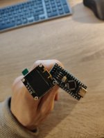
Guys, I buy arduino nano and oled display for her but I don't get it how to connect arduino and ours Dac? - There is a mention about LRCK pin on Dac but it needs to be more pins from arduino. Who can help with connection? The code is he:
DAC AD1862: Almost THT, I2S input, NOS, R-2R | Page 370 | diyAudio
I want to see the info about sample rate on display. I need for the Jlsound and Amanero transports.
Thanks!
DAC AD1862: Almost THT, I2S input, NOS, R-2R | Page 370 | diyAudio
I want to see the info about sample rate on display. I need for the Jlsound and Amanero transports.
Thanks!
Attachments
Last edited:
@sworder84
Display is connected on fast I2C output from arduino nano (pins SDA (A4) and SCL (A5) ... plus voltage and gnd pins) ... check if your display is for 3.3V or 5V power supply.
LRCK is connected on pin D2. GND from DAC must be also connected with arduino GND.
Display is connected on fast I2C output from arduino nano (pins SDA (A4) and SCL (A5) ... plus voltage and gnd pins) ... check if your display is for 3.3V or 5V power supply.
LRCK is connected on pin D2. GND from DAC must be also connected with arduino GND.
Attachments
- Home
- Source & Line
- Digital Line Level
- DAC AD1862: Almost THT, I2S input, NOS, R-2R